Page 1415 of 3342
B4M1222
E: INSTALLATION
1) Install ABSCM&H/U.
CAUTION:
Confirm that the specifications of the ABSCM&H/U
conforms to the vehicle specifications.
Tightening torque:
18±5 N⋅m (1.8±0.5 kg-m, 13.0±3.6 ft-lb)
2) Connect brake pipes to their correct ABSCM&H/U con-
nections.
3) Using cable clip, secure ABSCM&H/U harness to
bracket.
4) Connect connector to ABSCM&H/U.
CAUTION:
�Be sure to remove all foreign matter from inside the
connector before connecting.
�Ensure that the ABSCM&H/U connector is securely
locked.
5) Install air intake duct.
6) Connect ground cable to battery.
7) Bleed air from the brake system.
23. ABS Sensor (ABS 5.3i Type)
24. G Sensor (ABS 5.3i Type)
130
4-4SERVICE PROCEDURE
22. ABS Control Module and Hydraulic Control Unit (ABSCM&H/U) (ABS 5.3i Type) - 24. G Sensor (ABS 5.3i Type)
Page 1416 of 3342
B4M1222
E: INSTALLATION
1) Install ABSCM&H/U.
CAUTION:
Confirm that the specifications of the ABSCM&H/U
conforms to the vehicle specifications.
Tightening torque:
18±5 N⋅m (1.8±0.5 kg-m, 13.0±3.6 ft-lb)
2) Connect brake pipes to their correct ABSCM&H/U con-
nections.
3) Using cable clip, secure ABSCM&H/U harness to
bracket.
4) Connect connector to ABSCM&H/U.
CAUTION:
�Be sure to remove all foreign matter from inside the
connector before connecting.
�Ensure that the ABSCM&H/U connector is securely
locked.
5) Install air intake duct.
6) Connect ground cable to battery.
7) Bleed air from the brake system.
23. ABS Sensor (ABS 5.3i Type)
24. G Sensor (ABS 5.3i Type)
130
4-4SERVICE PROCEDURE
22. ABS Control Module and Hydraulic Control Unit (ABSCM&H/U) (ABS 5.3i Type) - 24. G Sensor (ABS 5.3i Type)
Page 1417 of 3342
B4M1222
E: INSTALLATION
1) Install ABSCM&H/U.
CAUTION:
Confirm that the specifications of the ABSCM&H/U
conforms to the vehicle specifications.
Tightening torque:
18±5 N⋅m (1.8±0.5 kg-m, 13.0±3.6 ft-lb)
2) Connect brake pipes to their correct ABSCM&H/U con-
nections.
3) Using cable clip, secure ABSCM&H/U harness to
bracket.
4) Connect connector to ABSCM&H/U.
CAUTION:
�Be sure to remove all foreign matter from inside the
connector before connecting.
�Ensure that the ABSCM&H/U connector is securely
locked.
5) Install air intake duct.
6) Connect ground cable to battery.
7) Bleed air from the brake system.
23. ABS Sensor (ABS 5.3i Type)
24. G Sensor (ABS 5.3i Type)
130
4-4SERVICE PROCEDURE
22. ABS Control Module and Hydraulic Control Unit (ABSCM&H/U) (ABS 5.3i Type) - 24. G Sensor (ABS 5.3i Type)
Page 1462 of 3342

1. Safety Precautions
1. HFC-134a AIR CONDITIONING SYSTEM
Component parts of the cooling system, refrigerant, com-
pressor oil, and other parts are not the same for the HFC-
134a system and the older CFC-12 system. Do not inter-
change parts or liquid.
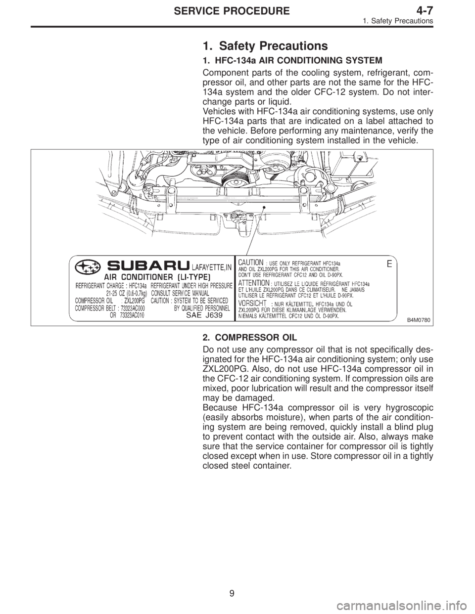
Vehicles with HFC-134a air conditioning systems, use only
HFC-134a parts that are indicated on a label attached to
the vehicle. Before performing any maintenance, verify the
type of air conditioning system installed in the vehicle.
B4M0780
2. COMPRESSOR OIL
Do not use any compressor oil that is not specifically des-
ignated for the HFC-134a air conditioning system; only use
ZXL200PG. Also, do not use HFC-134a compressor oil in
the CFC-12 air conditioning system. If compression oils are
mixed, poor lubrication will result and the compressor itself
may be damaged.
Because HFC-134a compressor oil is very hygroscopic
(easily absorbs moisture), when parts of the air condition-
ing system are being removed, quickly install a blind plug
to prevent contact with the outside air. Also, always make
sure that the service container for compressor oil is tightly
closed except when in use. Store compressor oil in a tightly
closed steel container.
9
4-7SERVICE PROCEDURE
1. Safety Precautions
Page 1464 of 3342

2. Basic Information
1) The combination of moisture and refrigerant forms acid,
therefore, moisture should not be allowed to enter the
refrigerant.
2) Refrigerant oil readily absorbs moisture, therefore, keep
refrigerant oil containers tightly capped.
3) The process of evacuating the system is performed to
remove small amounts of moisture. This is accomplished
by lowering the pressure inside the system, which allows
the moisture to boil off, in much the same way that a pot
of water will boil away to nothing given enough time. The
evacuation process does not suck the moisture out of the
system.
4) A minimum level of vacuum must be reached to satis-
factorily evacuate the system. This minimum level of
vacuum depends on the temperature inside the system.
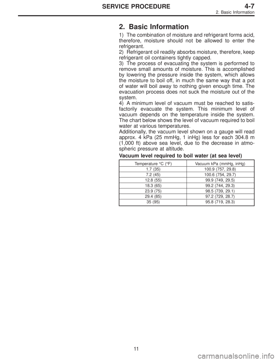
The chart below shows the level of vacuum required to boil
water at various temperatures.
Additionally, the vacuum level shown on a gauge will read
approx. 4 kPa (25 mmHg, 1 inHg) less for each 304.8 m
(1,000 ft) above sea level, due to the decrease in atmo-
spheric pressure at altitude.
Vacuum level required to boil water (at sea level)
Temperature°C(°F) Vacuum kPa (mmHg, inHg)
1.7 (35) 100.9 (757, 29.8)
7.2 (45) 100.6 (754, 29.7)
12.8 (55) 99.9 (749, 29.5)
18.3 (65) 99.2 (744, 29.3)
23.9 (75) 98.5 (739, 29.1)
29.4 (85) 97.2 (729, 28.7)
35 (95) 95.8 (719, 28.3)
11
4-7SERVICE PROCEDURE
2. Basic Information
Page 1476 of 3342

8. Leak Testing
The following points should be kept in mind when conduct-
ing a refrigerant leak test.
1) The A/C system to be tested must have an adequate
refrigerant charge to begin with.
2) The area where the leak test is conducted must be free
of wind and drafts, with still air being the ideal condition.
3) The atmosphere where the leak test is conducted must
be free of refrigerant contamination.
4) Operate the A/C system for approx. 10 minutes, then
turn the engine off an begin the leak test.
5) Refrigerant gas is heavier than air, therefore always
hold the probe below the connection being tested.
6) When checking for a leak along a length of hose or
tube, the leak detector probe must be moved slowly,
approx. 25 mm (1 in) per second making sure probe does
not come in contact with the component being tested.
7) When checking for a leak at a certain point, the leak
detector probe must be held at that point for at least 5
seconds.
G4M0609
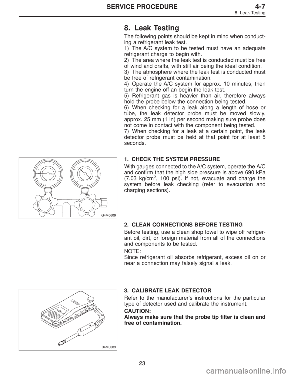
1. CHECK THE SYSTEM PRESSURE
With gauges connected to the A/C system, operate the A/C
and confirm that the high side pressure is above 690 kPa
(7.03 kg/cm
2, 100 psi). If not, evacuate and charge the
system before leak checking (refer to evacuation and
charging sections).
2. CLEAN CONNECTIONS BEFORE TESTING
Before testing, use a clean shop towel to wipe off refriger-
ant oil, dirt, or foreign material from all of the connections
and components to be tested.
NOTE:
Since refrigerant oil absorbs refrigerant, excess oil on or
near a connection may falsely signal a leak.
B4M0089
3. CALIBRATE LEAK DETECTOR
Refer to the manufacturer’s instructions for the particular
type of detector used and calibrate the instrument.
CAUTION:
Always make sure that the probe tip filter is clean and
free of contamination.
23
4-7SERVICE PROCEDURE
8. Leak Testing
Page 1726 of 3342
B6M0557A
2) Disconnect mass air flow sensor connector.
3) Remove four clips securing air cleaner upper cover.
B6M0558
4) Loosen the clamp screw and separate air cleaner upper
cover from air intake duct.
B6M0565A
5) Remove air cleaner element and air cleaner case.
B6M0566A
6) Remove #1 spark plug cord by pulling boot, not cord
itself.
B6M0567A
7) After connecting�1spark plug socket,�2extension and
�
3Universal Joint to each other, securely set them over the
spark plug in cylinder head.
8) Cover ABS pipes with rag to prevent damage.
�
1Spark plug socket 16 mm (5/8 in)
�
2Extension
�
3Universal Joint
�
4Extension
�
5Ratchet
30
6-1SERVICE PROCEDURE
3. Spark Plug
Page 1730 of 3342
![SUBARU LEGACY 1997 Service Repair Manual B6M0575A
5) Move washer tank upward.
B6M0563A
6) Remove #4 spark plug cord by pulling boot, not cord
itself.
7) For subsequent procedures, refer to the procedure for
#1 spark plug. <Ref. to 6-1 [W3E1] SUBARU LEGACY 1997 Service Repair Manual B6M0575A
5) Move washer tank upward.
B6M0563A
6) Remove #4 spark plug cord by pulling boot, not cord
itself.
7) For subsequent procedures, refer to the procedure for
#1 spark plug. <Ref. to 6-1 [W3E1]](/manual-img/17/57434/w960_57434-1729.png)
B6M0575A
5) Move washer tank upward.
B6M0563A
6) Remove #4 spark plug cord by pulling boot, not cord
itself.
7) For subsequent procedures, refer to the procedure for
#1 spark plug.
CAUTION:
When removing spark plug, cover the ATF cooling
pipes with a rag to prevent damage.
B6M0572A
NOTE:
For easier removal of spark plug, diagonally insert the tools
from the direction of battery stand into plug hole as shown
in figure.
B6M0573
F: INSTALLATION (2500 cc OUTBACK
MODEL)
1. #1 SPARK PLUG
1) After setting spark plug in spark plug socket, connect
the spark plug socket, extension and Universal Joint to
each other.
2) Screw spark plug into cylinder head using the con-
nected tools above mentioned. At this point, it is necessary
to support the rear end of the tools with fingertips.
3) When spark plug is screwed in two or three turns, tem-
porarily disconnect the tools connected in step 1) above.
4) Confirm that spark plug is screwed into the cylinder
head properly by touching it with finger. If it is difficult to
reach it by hand, confirm its condition by using mirror and
suchlike.
5) Cover ABS pipes with rag to prevent damage.
34
6-1SERVICE PROCEDURE
3. Spark Plug