Page 1399 of 3342
 Under the TCS sequence control, after the hydraulic
unit solenoid valve is driven, the operation of the hydraulic
unit can be checked by means of the brake tester or pres-
s")
F: TCS SEQUENCE CONTROL
1) Under the TCS sequence control, after the hydraulic
unit solenoid valve is driven, the operation of the hydraulic
unit can be checked by means of the brake tester or pres-
sure gauge.
2) TCS sequence control can be started by diagnosis con-
nector or select monitor.
B4M0082C
1. OPERATIONAL GUIDELINES OF THE TCS
SEQUENCE CONTROL WITH DIAGNOSIS
CONNECTOR
1) Connect diagnosis terminals to terminal No. 4 of the
diagnosis connector beside driver seat heater unit.
2) Ignition switch is turned to ON.
3) Make sure only the start code (code 11) is shown in
normal condition.
NOTE:
When trouble codes are stored in memory, repair the faulty
parts.
4) Set the speed of all wheels at 10 km/h (6 MPH) or less.
5) Turn ignition switch OFF.
6) Start engine, and within 0.5 seconds after the ABS
warning light and TCS warning light go out, press TCS OFF
switch. Within 1.0 second thereafter, release and press the
switch again. Then, keep the switch pressed.
NOTE:
�When the TCS sequence control is set to on, the brake
pedal must not be depressed.
�Engine must operate.
�When TCS OFF switch is not depressed within 0.5 sec-
onds after ABS and TCS warning lights turn off, the trouble
code mode comes on.
7) After completion of TCS sequence control, turn ignition
switch OFF.
11 5
4-4SERVICE PROCEDURE
20. Hydraulic Unit for ABS/TCS System
Page 1400 of 3342
2. OPERATIONAL GUIDELINES OF THE TCS
SEQUENCE CONTROL WITH SELECT MONITOR
1) Connect select monitor to data link connector beside
driver’s seat heater unit.
2) Engine starts.
3) Put select monitor to TCS mode.
4) Put select monitor to FBI mode. Make sure code 11 is
indicated.
NOTE:
When trouble codes are stored in memory, repair the faulty
parts.
B4M0639
5) Press FD2 ENT key.
B4M0624
6) When the message shown in the figure is displayed,
press ENT key.
7) Checked portions will be displayed on select monitor.
B4M0627
8) When TCS sequence control cannot be started (by sys-
tem malfunction, etc.), the message shown in the figure will
be displayed.
NOTE:
Read the trouble codes. Repair faulty parts.
11 6
4-4SERVICE PROCEDURE
20. Hydraulic Unit for ABS/TCS System
Page 1401 of 3342
3. CONDITIONS FOR COMPLETION OF TCS
SEQUENCE CONTROL
When the following conditions develop, the TCS sequence
control stops and ABS and TCS warning lights come on
while the ABS and TCS function will then stop. The brake
system functions as a conventional brake system.
1) When the speed of at least one wheel reaches 10 km/h
(6 MPH).
2) When terminal No. 4 is separated from ground. (When
select monitor is not used.)
3) When the brake pedal is depressed during sequence
control and the braking lamp switch is set to ON.
4) When TCS OFF switch is released. (When select moni-
tor is not used.)
5) After completion of the TCS sequence control.
6) When output signal to break TCS control is emitted from
ECM.
7) When malfunction is detected.
NOTE:
When malfunction has been detected and the TCS
sequence control operation has stopped, the trouble codes
are stored in memory.
11 7
4-4SERVICE PROCEDURE
20. Hydraulic Unit for ABS/TCS System
Page 1402 of 3342
4. CONDITIONS FOR TCS SEQUENCE CONTROL
B4M0642A
NOTE:
When select monitor is used, control operation starts at
point A. It is not required to operate TCS OFF switch for
starting control operation. The patterns from IGN key ON
to point A show operation is started by diagnosis connec-
tor.
11 8
4-4SERVICE PROCEDURE
20. Hydraulic Unit for ABS/TCS System
Page 1403 of 3342
B4M0628
G: INSTALLATION
1) Install hydraulic unit and bracket.
Tightening torque:
32±7 N⋅m (3.3±0.7 kg-m, 23.9±5.1 ft-lb)
2) Connect brake pipes to their correct hydraulic unit con-
nections.
3) Connect connector to hydraulic unit.
4) Install canister.
5) Install air cleaner case.
6) Install air intake duct.
7) Connect ground cable to battery.
CAUTION:
Cover relay securely with rubber boot.
21. ABS/TCS Control Module
A: REMOVAL
1) Disconnect ground cable from battery.
2) Remove floor mat located under lower right side of front
seat.
B4M0643A
3) Remove screw which secure ABS/TCS control module
from the body.
4) Disconnect connector from ABS/TCS control module.
B: INSPECTION
Check that connector is connected correctly and that con-
nector terminal sliding resistance is correct.
11 9
4-4SERVICE PROCEDURE
20. Hydraulic Unit for ABS/TCS System - 21. ABS/TCS Control Module
Page 1404 of 3342
B4M0628
G: INSTALLATION
1) Install hydraulic unit and bracket.
Tightening torque:
32±7 N⋅m (3.3±0.7 kg-m, 23.9±5.1 ft-lb)
2) Connect brake pipes to their correct hydraulic unit con-
nections.
3) Connect connector to hydraulic unit.
4) Install canister.
5) Install air cleaner case.
6) Install air intake duct.
7) Connect ground cable to battery.
CAUTION:
Cover relay securely with rubber boot.
21. ABS/TCS Control Module
A: REMOVAL
1) Disconnect ground cable from battery.
2) Remove floor mat located under lower right side of front
seat.
B4M0643A
3) Remove screw which secure ABS/TCS control module
from the body.
4) Disconnect connector from ABS/TCS control module.
B: INSPECTION
Check that connector is connected correctly and that con-
nector terminal sliding resistance is correct.
11 9
4-4SERVICE PROCEDURE
20. Hydraulic Unit for ABS/TCS System - 21. ABS/TCS Control Module
Page 1405 of 3342
C: INSTALLATION
1) Connect connector to ABS/TCS control module.
2) Install ABS/TCS control module on the body.
CAUTION:
�When installing seat rail, be careful no to have the
harness caught in the rail.
�Cover the connector completely with rubber boot.
120
4-4SERVICE PROCEDURE
21. ABS/TCS Control Module
Page 1406 of 3342
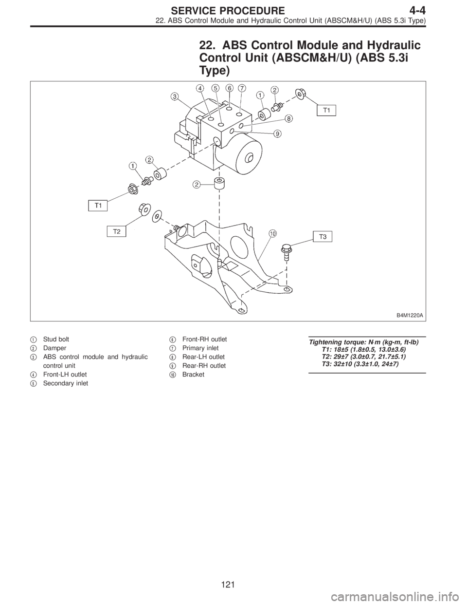
22. ABS Control Module and Hydraulic
Control Unit (ABSCM&H/U) (ABS 5.3i
Type)
B4M1220A
�1Stud bolt
�
2Damper
�
3ABS control module and hydraulic
control unit
�
4Front-LH outlet
�
5Secondary inlet�
6Front-RH outlet
�
7Primary inlet
�
8Rear-LH outlet
�
9Rear-RH outlet
�
10Bracket
Tightening torque: N⋅m (kg-m, ft-lb)
T1: 18±5 (1.8±0.5, 13.0±3.6)
T2: 29±7 (3.0±0.7, 21.7±5.1)
T3: 32±10 (3.3±1.0, 24±7)
121
4-4SERVICE PROCEDURE
22. ABS Control Module and Hydraulic Control Unit (ABSCM&H/U) (ABS 5.3i Type)
![SUBARU LEGACY 1997 Service Repair Manual 2. OPERATIONAL GUIDELINES OF THE TCS
SEQUENCE CONTROL WITH SELECT MONITOR
1) Connect select monitor to data link connector beside
driver’s seat heater unit. <Ref. to 4-4 [W19D0] step 1).>
2) Engine](/manual-img/17/57434/w960_57434-1399.png "SUBARU LEGACY 1997 Service Repair Manual 2. OPERATIONAL GUIDELINES OF THE TCS
SEQUENCE CONTROL WITH SELECT MONITOR
1) Connect select monitor to data link connector beside
driver’s seat heater unit. <Ref. to 4-4 [W19D0] step 1).>
2) Engine")


 Install hydraulic unit and bracket.
Tightening torque:
32±7 N⋅m (3.3±0.7 kg-m, 23.9±5.1 ft-lb)
2) Connect brake pipes to their correct hydraulic unit con-
nections. <Re")
 Install hydraulic unit and bracket.
Tightening torque:
32±7 N⋅m (3.3±0.7 kg-m, 23.9±5.1 ft-lb)
2) Connect brake pipes to their correct hydraulic unit con-
nections. <Re")