Page 1907 of 3342
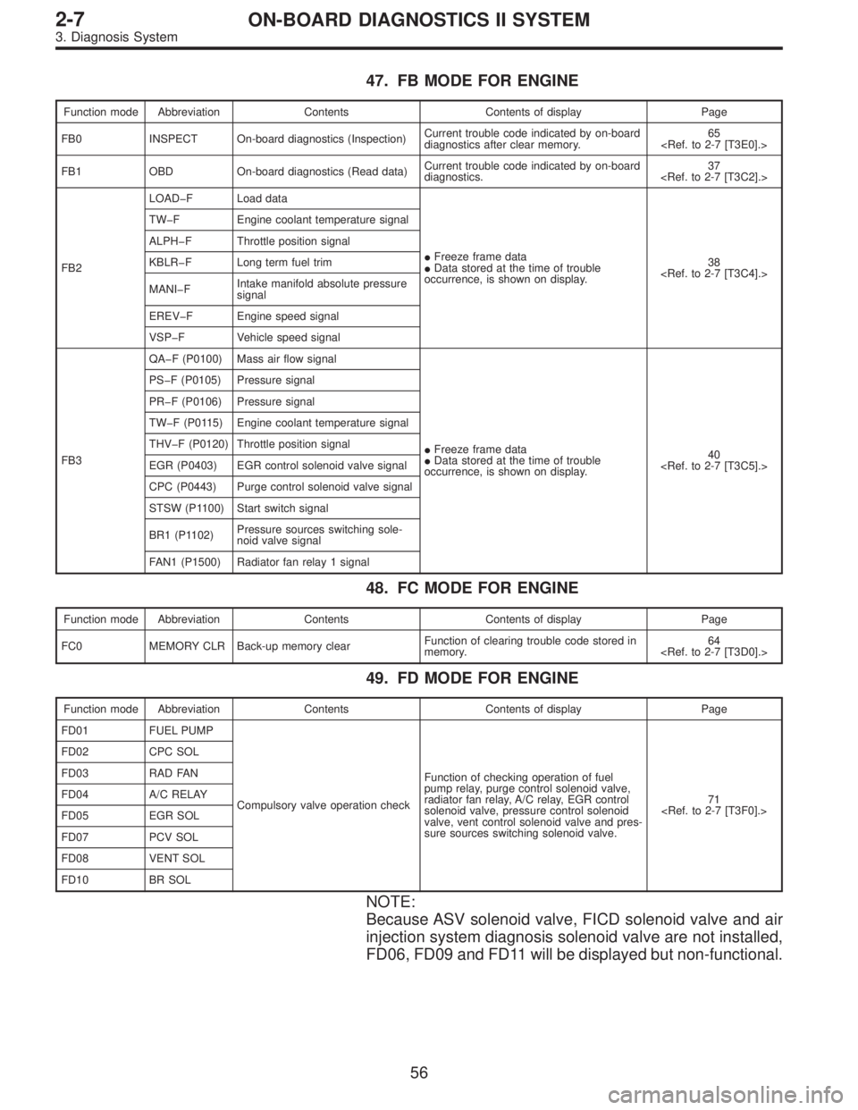
47. FB MODE FOR ENGINE
Function mode Abbreviation Contents Contents of display Page
FB0 INSPECT On-board diagnostics (Inspection)Current trouble code indicated by on-board
diagnostics after clear memory.65
FB1 OBD On-board diagnostics (Read data)Current trouble code indicated by on-board
diagnostics.37
FB2LOAD�F Load data
�Freeze frame data
�Data stored at the time of trouble
occurrence, is shown on display.38
TW�F Engine coolant temperature signal
ALPH�F Throttle position signal
KBLR�F Long term fuel trim
MANI�FIntake manifold absolute pressure
signal
EREV�F Engine speed signal
VSP�F Vehicle speed signal
FB3QA�F (P0100) Mass air flow signal
�Freeze frame data
�Data stored at the time of trouble
occurrence, is shown on display.40
PS�F (P0105) Pressure signal
PR�F (P0106) Pressure signal
TW�F (P0115) Engine coolant temperature signal
THV�F (P0120) Throttle position signal
EGR (P0403) EGR control solenoid valve signal
CPC (P0443) Purge control solenoid valve signal
STSW (P1100) Start switch signal
BR1 (P1102)Pressure sources switching sole-
noid valve signal
FAN1 (P1500) Radiator fan relay 1 signal
48. FC MODE FOR ENGINE
Function mode Abbreviation Contents Contents of display Page
FC0 MEMORY CLR Back-up memory clearFunction of clearing trouble code stored in
memory.64
49. FD MODE FOR ENGINE
Function mode Abbreviation Contents Contents of display Page
FD01 FUEL PUMP
Compulsory valve operation checkFunction of checking operation of fuel
pump relay, purge control solenoid valve,
radiator fan relay, A/C relay, EGR control
solenoid valve, pressure control solenoid
valve, vent control solenoid valve and pres-
sure sources switching solenoid valve.71
FD02 CPC SOL
FD03 RAD FAN
FD04 A/C RELAY
FD05 EGR SOL
FD07 PCV SOL
FD08 VENT SOL
FD10 BR SOL
NOTE:
Because ASV solenoid valve, FICD solenoid valve and air
injection system diagnosis solenoid valve are not installed,
FD06, FD09 and FD11 will be displayed but non-functional.
56
2-7ON-BOARD DIAGNOSTICS II SYSTEM
3. Diagnosis System
Page 1914 of 3342
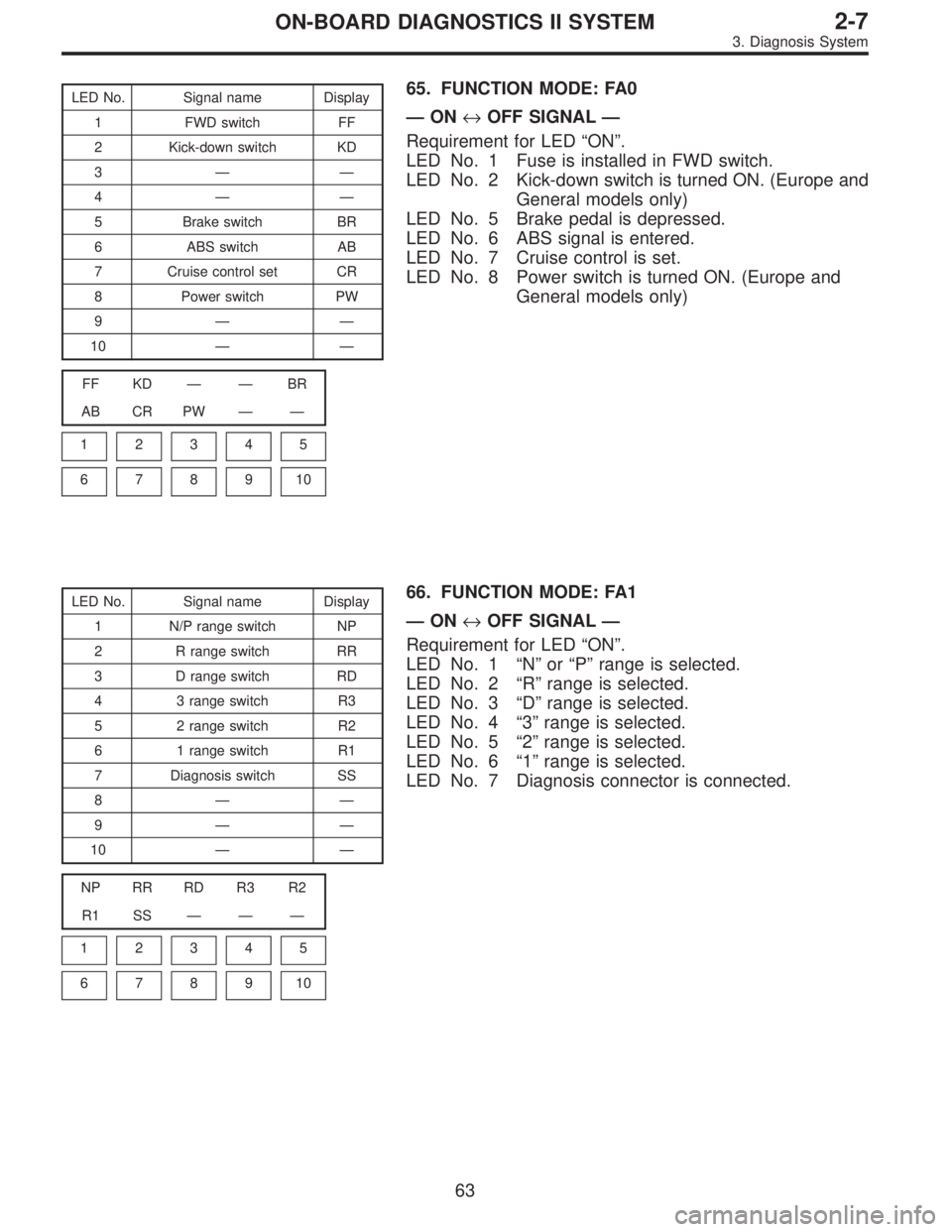
LED No. Signal name Display
1 FWD switch FF
2 Kick-down switch KD
3——
4——
5 Brake switch BR
6 ABS switch AB
7 Cruise control set CR
8 Power switch PW
9——
10——
FF KD——BR
AB CR PW——
1
2345
678910
65. FUNCTION MODE: FA0
—ON↔OFF SIGNAL—
Requirement for LED“ON”.
LED No. 1 Fuse is installed in FWD switch.
LED No. 2 Kick-down switch is turned ON. (Europe and
General models only)
LED No. 5 Brake pedal is depressed.
LED No. 6 ABS signal is entered.
LED No. 7 Cruise control is set.
LED No. 8 Power switch is turned ON. (Europe and
General models only)
LED No. Signal name Display
1 N/P range switch NP
2 R range switch RR
3 D range switch RD
4 3 range switch R3
5 2 range switch R2
6 1 range switch R1
7 Diagnosis switch SS
8——
9——
10——
NP RR RD R3 R2
R1 SS———
1
2345
678910
66. FUNCTION MODE: FA1
—ON↔OFF SIGNAL—
Requirement for LED“ON”.
LED No. 1“N”or“P”range is selected.
LED No. 2“R”range is selected.
LED No. 3“D”range is selected.
LED No. 4“3”range is selected.
LED No. 5“2”range is selected.
LED No. 6“1”range is selected.
LED No. 7 Diagnosis connector is connected.
63
2-7ON-BOARD DIAGNOSTICS II SYSTEM
3. Diagnosis System
Page 1920 of 3342
NOTE:
�On AWD vehicles, release the parking brake.
�The speed difference between front and rear wheels
may light either the ABS or the ABS/TCS warning light, but
this indicates no malfunctions. When engine control diag-
nosis is finished, perform the ABS or the ABS/TCS memory
clearance procedure of self-diagnosis system.
4-4b [T6D2] or [T9K0], or 4-4c [T6D2] or [T9J0], or 4-4d
[T6D2] or [T9J0].>
OBD0005H
B2M0432D
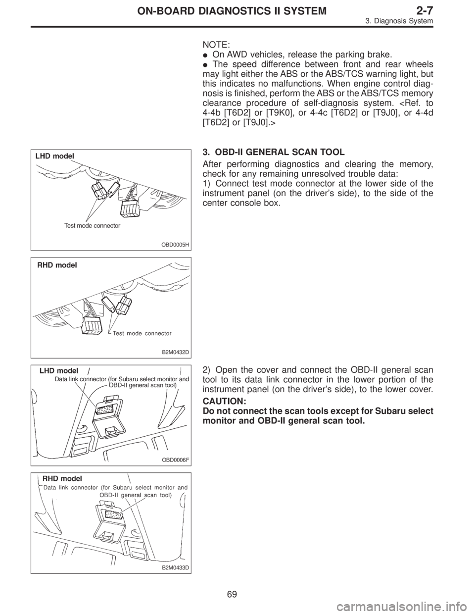
3. OBD-II GENERAL SCAN TOOL
After performing diagnostics and clearing the memory,
check for any remaining unresolved trouble data:
1) Connect test mode connector at the lower side of the
instrument panel (on the driver’s side), to the side of the
center console box.
OBD0006F
B2M0433D
2) Open the cover and connect the OBD-II general scan
tool to its data link connector in the lower portion of the
instrument panel (on the driver’s side), to the lower cover.
CAUTION:
Do not connect the scan tools except for Subaru select
monitor and OBD-II general scan tool.
69
2-7ON-BOARD DIAGNOSTICS II SYSTEM
3. Diagnosis System
Page 1921 of 3342
3) Start the engine.
NOTE:
�Ensure the selector lever is placed in the“P”position
before starting. (AT vehicles)
�Depress clutch pedal when starting the engine. (MT
vehicles)
4) Using the selector lever or shift lever, turn the“P”posi-
tion switch and the“N”position switch to ON.
5) Depress the brake pedal to turn the brake switch ON.
(AT vehicles)
6) Keep engine speed in the 2,500—3,000 rpm range for
40 seconds.
NOTE:
On models without tachometer, use the Subaru select
monitor or tachometer (Secondary pickup type).
7) Place the selector lever or shift lever in the“D”position
(AT vehicles) or“1st”gear (MT vehicles) and drive the
vehicle at 5 to 10 km/h (3 to 6 MPH).
NOTE:
�On AWD vehicles, release the parking brake.
�The speed difference between front and rear wheels
may light either the ABS or the ABS/TCS warning light, but
this indicates no malfunctions. When engine control diag-
nosis is finished, perform the ABS or the ABS/TCS memory
clearance procedure of self-diagnosis system.
4-4b [T6D2] or [T9K0], or 4-4c [T6D2] or [T9J0], or 4-4d
[T6D2] or [T9J0].>
8) Using the OBD-II general scan tool, check for diagnos-
tic trouble code(s) and record the result(s).
NOTE:
�For detailed operation procedures, refer to the OBD-II
General Scan Tool Instruction Manual.
�For details concerning diagnostic trouble codes, refer to
the DIAGNOSTIC TROUBLE CODE (DTC) LIST.
2-7 [T10A0], [T11A0].>
H2M1149
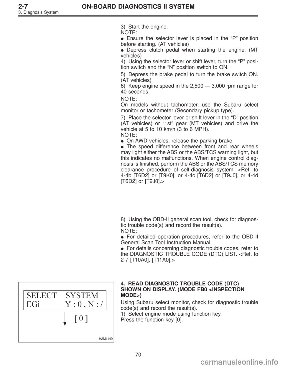
4. READ DIAGNOSTIC TROUBLE CODE (DTC)
SHOWN ON DISPLAY. (MODE FB0
MODE>)
Using Subaru select monitor, check for diagnostic trouble
code(s) and record the result(s).
1) Select engine mode using function key.
Press the function key [0].
70
2-7ON-BOARD DIAGNOSTICS II SYSTEM
3. Diagnosis System
Page 1929 of 3342
14) In AT vehicles, do not continue the stall for more than
five seconds at a time (from closed throttle, fully open
throttle to stall engine speed).
15) On ABS or ABS/TCS vehicle, when performing driving
test in jacked-up or lifted-up position, sometimes the warn-
ing light may be lit, but this is not a malfunction of the sys-
tem. The reason for this is the speed difference between
the front and rear wheels. After diagnosis of engine control
system, perform the ABS or ABS/TCS memory clearance
procedure of self-diagnosis system.
[T9K0], or 4-4c [T6D2] or [T9J0], or 4-4d [T6D2] or [T9J0].>
C: PRE-INSPECTION
Before performing diagnostics, check the following items
which might affect engine problems:
1. POWER SUPPLY
1) Measure battery voltage and specific gravity of electro-
lyte.
Standard voltage: 12 V
Specific gravity: Above 1.260
2) Check the condition of the main and other fuses, and
harnesses and connectors. Also check for proper ground-
ing.
B2M0648A
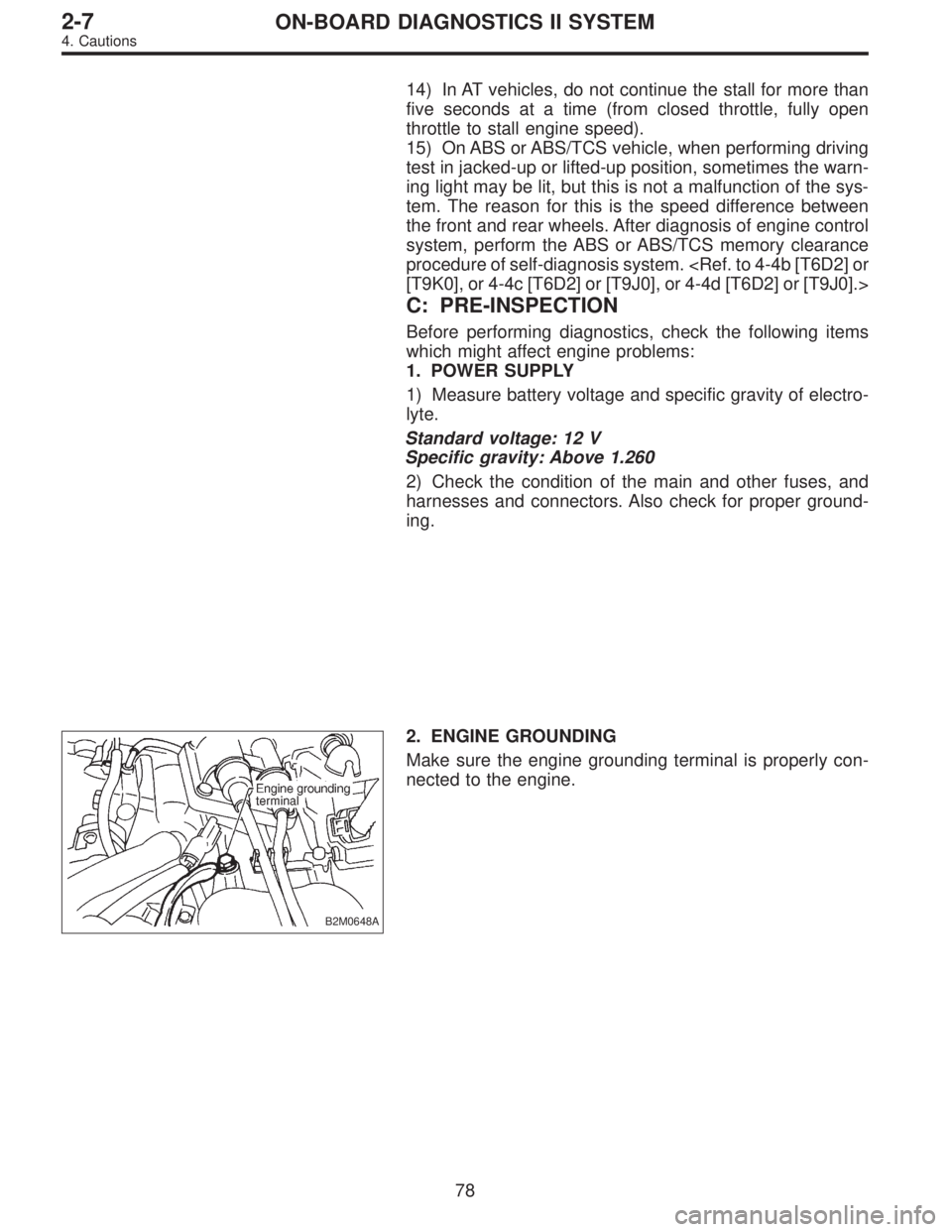
2. ENGINE GROUNDING
Make sure the engine grounding terminal is properly con-
nected to the engine.
78
2-7ON-BOARD DIAGNOSTICS II SYSTEM
4. Cautions
Page 1933 of 3342
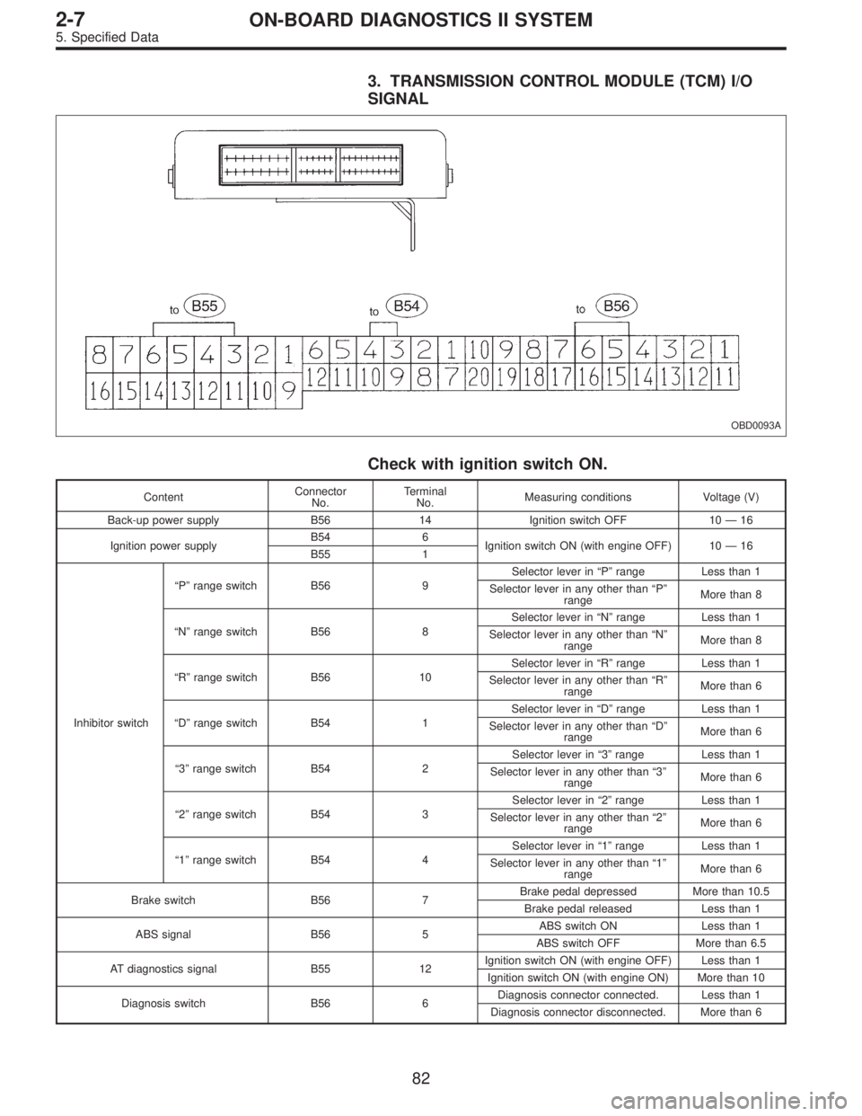
3. TRANSMISSION CONTROL MODULE (TCM) I/O
SIGNAL
OBD0093A
Check with ignition switch ON.
ContentConnector
No.Terminal
No.Measuring conditions Voltage (V)
Back-up power supply B56 14 Ignition switch OFF 10—16
Ignition power supplyB54 6
Ignition switch ON (with engine OFF) 10—16
B55 1
Inhibitor switch“P”range switch B56 9Selector lever in“P”range Less than 1
Selector lever in any other than“P”
rangeMore than 8
“N”range switch B56 8Selector lever in“N”range Less than 1
Selector lever in any other than“N”
rangeMore than 8
“R”range switch B56 10Selector lever in“R”range Less than 1
Selector lever in any other than“R”
rangeMore than 6
“D”range switch B54 1Selector lever in“D”range Less than 1
Selector lever in any other than“D”
rangeMore than 6
“3”range switch B54 2Selector lever in“3”range Less than 1
Selector lever in any other than“3”
rangeMore than 6
“2”range switch B54 3Selector lever in“2”range Less than 1
Selector lever in any other than“2”
rangeMore than 6
“1”range switch B54 4Selector lever in“1”range Less than 1
Selector lever in any other than“1”
rangeMore than 6
Brake switch B56 7Brake pedal depressed More than 10.5
Brake pedal released Less than 1
ABS signal B56 5ABS switch ON Less than 1
ABS switch OFF More than 6.5
AT diagnostics signal B55 12Ignition switch ON (with engine OFF) Less than 1
Ignition switch ON (with engine ON) More than 10
Diagnosis switch B56 6Diagnosis connector connected. Less than 1
Diagnosis connector disconnected. More than 6
82
2-7ON-BOARD DIAGNOSTICS II SYSTEM
5. Specified Data
Page 1938 of 3342
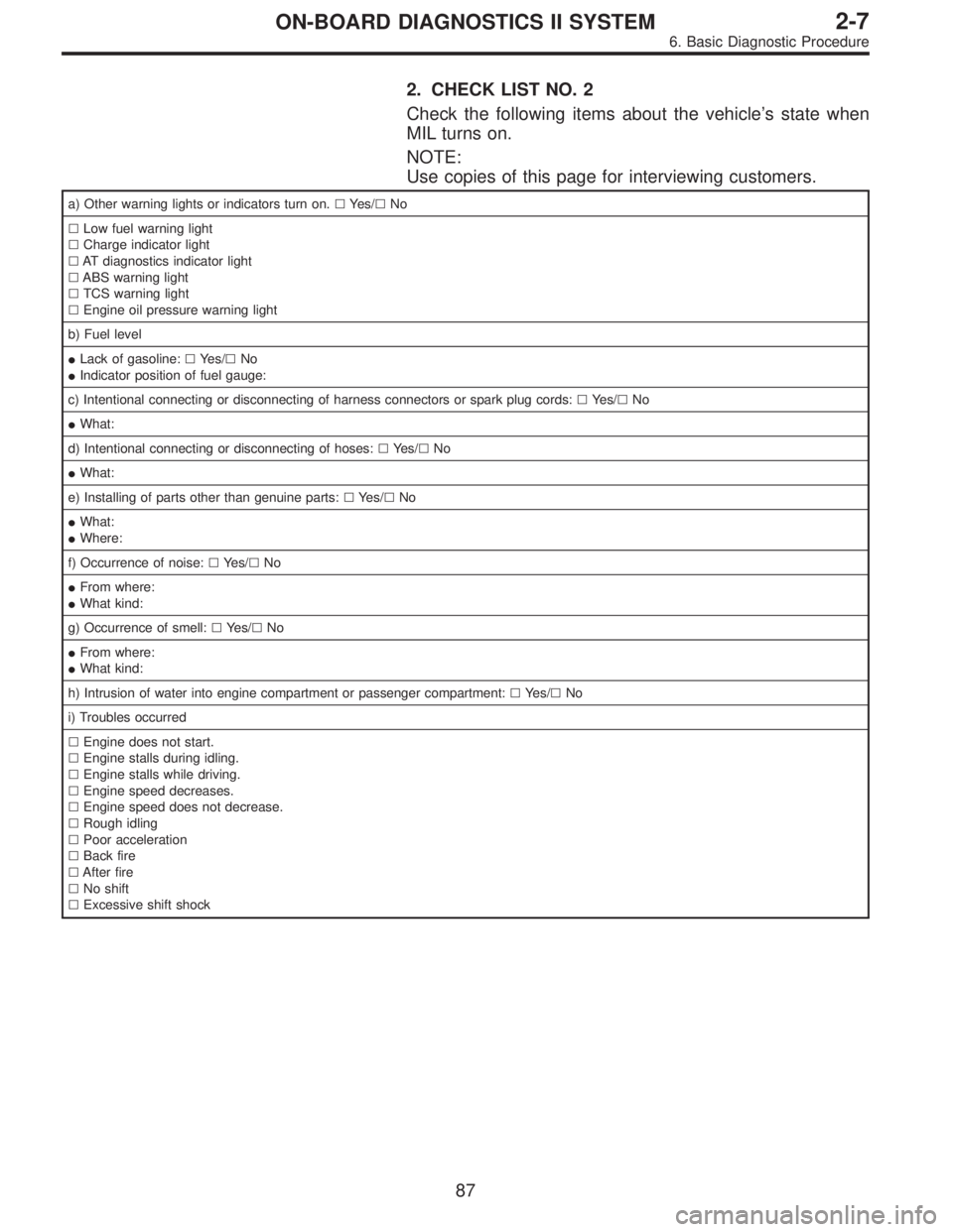
2. CHECK LIST NO. 2
Check the following items about the vehicle’s state when
MIL turns on.
NOTE:
Use copies of this page for interviewing customers.
a) Other warning lights or indicators turn on.�Yes/�No
�Low fuel warning light
�Charge indicator light
�AT diagnostics indicator light
�ABS warning light
�TCS warning light
�Engine oil pressure warning light
b) Fuel level
�Lack of gasoline:�Yes/�No
�Indicator position of fuel gauge:
c) Intentional connecting or disconnecting of harness connectors or spark plug cords:�Yes/�No
�What:
d) Intentional connecting or disconnecting of hoses:�Yes/�No
�What:
e) Installing of parts other than genuine parts:�Yes/�No
�What:
�Where:
f) Occurrence of noise:�Yes/�No
�From where:
�What kind:
g) Occurrence of smell:�Yes/�No
�From where:
�What kind:
h) Intrusion of water into engine compartment or passenger compartment:�Yes/�No
i) Troubles occurred
�Engine does not start.
�Engine stalls during idling.
�Engine stalls while driving.
�Engine speed decreases.
�Engine speed does not decrease.
�Rough idling
�Poor acceleration
�Back fire
�After fire
�No shift
�Excessive shift shock
87
2-7ON-BOARD DIAGNOSTICS II SYSTEM
6. Basic Diagnostic Procedure
Page 2217 of 3342
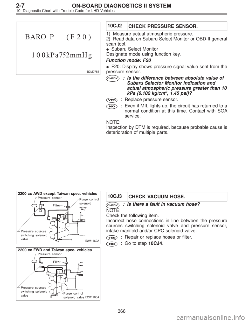
B2M0755
10CJ2
CHECK PRESSURE SENSOR.
1) Measure actual atmospheric pressure.
2) Read data on Subaru Select Monitor or OBD-II general
scan tool.
�Subaru Select Monitor
Designate mode using function key.
Function mode: F20
�F20: Display shows pressure signal value sent from the
pressure sensor.
: Is the difference between absolute value of
Subaru Selector Monitor indication and
actual atmospheric pressure greater than 10
kPa (0.102 kg/cm
2, 1.45 psi)?
: Replace pressure sensor.
: Even if MIL lights up, the circuit has returned to a
normal condition at this time. Contact with SOA
service.
NOTE:
Inspection by DTM is required, because probable cause is
deterioration of multiple parts.
B2M1162A
B2M1163A
10CJ3
CHECK VACUUM HOSE.
: Is there a fault in vacuum hose?
NOTE:
Check the following item.
Incorrect hose connections in line between the pressure
sources switching solenoid valve and pressure sensor,
intake manifold and/or CPC solenoid valve.
: Repair or replace hoses or filter.
: Go to step10CJ4.
366
2-7ON-BOARD DIAGNOSTICS II SYSTEM
10. Diagnostic Chart with Trouble Code for LHD Vehicles