Page 2469 of 3342

DISPLAY
LED No. Signal name Symbol
1 FWD switch FF
2 Kick-down switch KD
3——
4——
5 Brake BR
6 ABS switch AB
7 Cruise control set CR
8 Power switch PW
9——
10——
FF KD—— ——BR
AB CR PW—— ——
1
2345
678910
P: MODE FA0
—SWITCH 1 (SW1)—
Reference values
�Lights up when the fuse is installed in FWD switch (No. 1).
�Light up when the brake pedal is depressed (No. 5).
�Light up when the ABS signal is entered (No. 6).
�Lights up when the cruise control is set (No. 7).
NOTE:
LED Nos. 2 and 8 do not come on.
DISPLAY
LED No. Signal name Symbol
1 N/P range switch NP
2 R range switch RR
3 D range switch RD
4 3 range switch R3
5 2 range switch R2
6 1 range switch R1
7 Diagnosis switch SS
8——
9——
10——
NP RR RD R3 R2
R1 SS—— —— ——
1
2345
678910
Q: MODE FA1
—SWITCH 2 (SW2)—
Reference values
�Lights up when the N or P range is selected (No. 1).
�Lights up when the R range is selected (No. 2).
�Lights up when the D range is selected (No. 3).
�Lights up when the 3 range is selected (No. 4).
�Lights up when the 2 range is selected (No. 5).
�Lights up when the 1 range is selected (No. 6).
�Lights up when the diagnosis switch is connected
(No. 7).
NOTE:
If each LED does not illuminate in the above conditions,
inhibitor switch malfunction may occur. Perform diagnostics
on inhibitor switch.
65
3-2AUTOMATIC TRANSMISSION AND DIFFERENTIAL
8. Diagnostic Chart with Select Monitor
Page 2477 of 3342

1. Supplemental Restraint System
“Airbag”
Airbag system wiring harness is routed near the ABS/TCS
control module, ABS sensor and hydraulic control unit.
CAUTION:
�All Airbag system wiring harness and connectors
are colored yellow. Do not use electrical test equip-
ment on these circuit.
�Be careful not to damage Airbag system wiring har-
ness when servicing the ABS/TCS control module,
ABS sensor and hydraulic control unit.
2. Pre-inspection
Before performing diagnostics, check the following items
which might affect ABS/TCS problems:
A: MECHANICAL INSPECTION
1. POWER SUPPLY
1) Measure battery voltage and specific gravity of electro-
lyte.
Standard voltage: 12 V, or more
Specific gravity: Above 1.260
2) Check the condition of the main and other fuses, and
harnesses and connectors. Also check for proper ground-
ing.
2. BRAKE FLUID
1) Check brake fluid level.
2) Check brake fluid leakage.
3. BRAKE DRAG
Check brake drag.
4. BRAKE PAD AND ROTOR
Check brake pad and rotor.
5. TIRE SPECIFICATIONS, TIRE WEAR AND AIR
PRESSURE
Check tire specifications, tire wear and air pressure.
to 4-2 [S1A0].>
2
4-4bBRAKES
1. Supplemental Restraint System“Airbag”- 2. Pre-inspection
Page 2478 of 3342

1. Supplemental Restraint System
“Airbag”
Airbag system wiring harness is routed near the ABS/TCS
control module, ABS sensor and hydraulic control unit.
CAUTION:
�All Airbag system wiring harness and connectors
are colored yellow. Do not use electrical test equip-
ment on these circuit.
�Be careful not to damage Airbag system wiring har-
ness when servicing the ABS/TCS control module,
ABS sensor and hydraulic control unit.
2. Pre-inspection
Before performing diagnostics, check the following items
which might affect ABS/TCS problems:
A: MECHANICAL INSPECTION
1. POWER SUPPLY
1) Measure battery voltage and specific gravity of electro-
lyte.
Standard voltage: 12 V, or more
Specific gravity: Above 1.260
2) Check the condition of the main and other fuses, and
harnesses and connectors. Also check for proper ground-
ing.
2. BRAKE FLUID
1) Check brake fluid level.
2) Check brake fluid leakage.
3. BRAKE DRAG
Check brake drag.
4. BRAKE PAD AND ROTOR
Check brake pad and rotor.
5. TIRE SPECIFICATIONS, TIRE WEAR AND AIR
PRESSURE
Check tire specifications, tire wear and air pressure.
to 4-2 [S1A0].>
2
4-4bBRAKES
1. Supplemental Restraint System“Airbag”- 2. Pre-inspection
Page 2479 of 3342
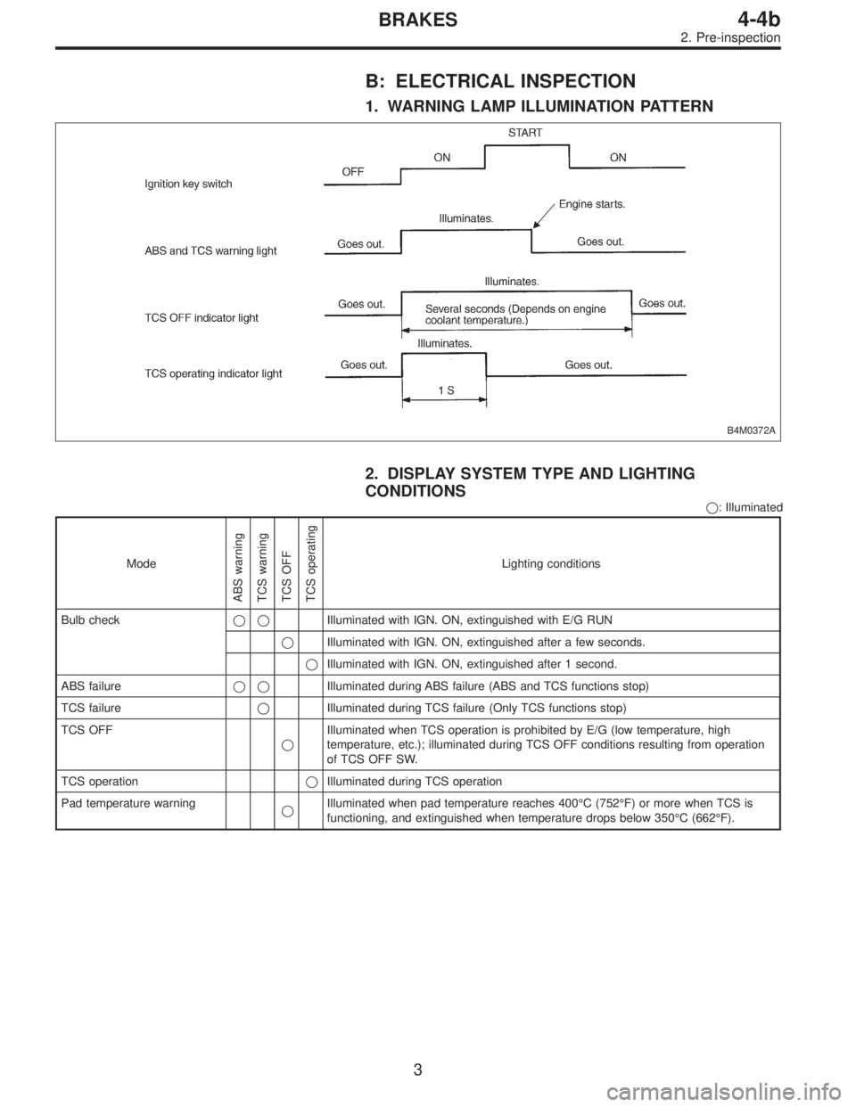
B: ELECTRICAL INSPECTION
1. WARNING LAMP ILLUMINATION PATTERN
B4M0372A
2. DISPLAY SYSTEM TYPE AND LIGHTING
CONDITIONS
�: Illuminated
Mode
ABS warning
TCS warning
TCS OFF
TCS operating
Lighting conditions
Bulb check��Illuminated with IGN. ON, extinguished with E/G RUN
�Illuminated with IGN. ON, extinguished after a few seconds.
�Illuminated with IGN. ON, extinguished after 1 second.
ABS failure��Illuminated during ABS failure (ABS and TCS functions stop)
TCS failure�Illuminated during TCS failure (Only TCS functions stop)
TCS OFF
�Illuminated when TCS operation is prohibited by E/G (low temperature, high
temperature, etc.); illuminated during TCS OFF conditions resulting from operation
of TCS OFF SW.
TCS operation�Illuminated during TCS operation
Pad temperature warning
�Illuminated when pad temperature reaches 400°C (752°F) or more when TCS is
functioning, and extinguished when temperature drops below 350°C (662°F).
3
4-4bBRAKES
2. Pre-inspection
Page 2480 of 3342
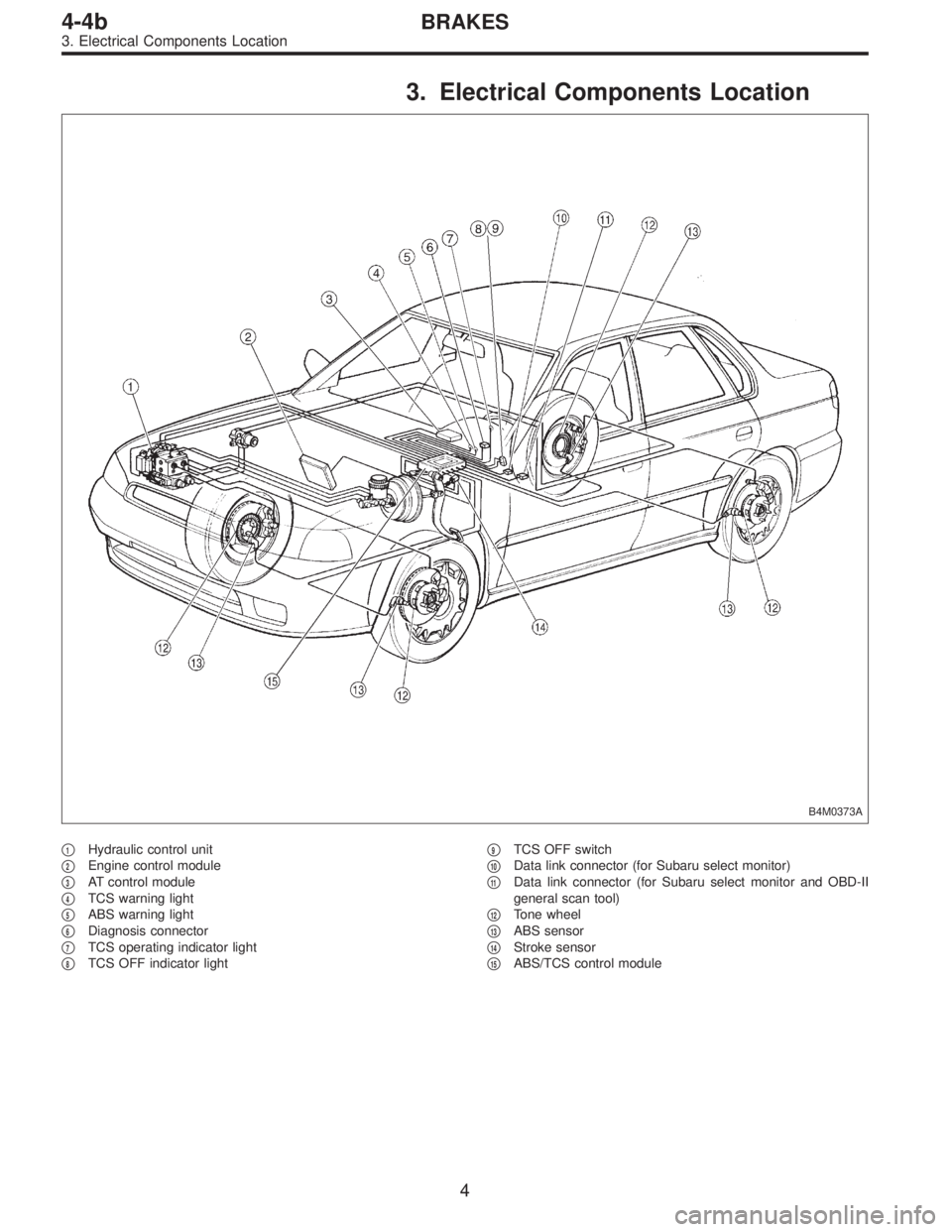
3. Electrical Components Location
B4M0373A
�1Hydraulic control unit
�
2Engine control module
�
3AT control module
�
4TCS warning light
�
5ABS warning light
�
6Diagnosis connector
�
7TCS operating indicator light
�
8TCS OFF indicator light�
9TCS OFF switch
�
10Data link connector (for Subaru select monitor)
�
11Data link connector (for Subaru select monitor and OBD-II
general scan tool)
�
12Tone wheel
�
13ABS sensor
�
14Stroke sensor
�
15ABS/TCS control module
4
4-4bBRAKES
3. Electrical Components Location
Page 2482 of 3342
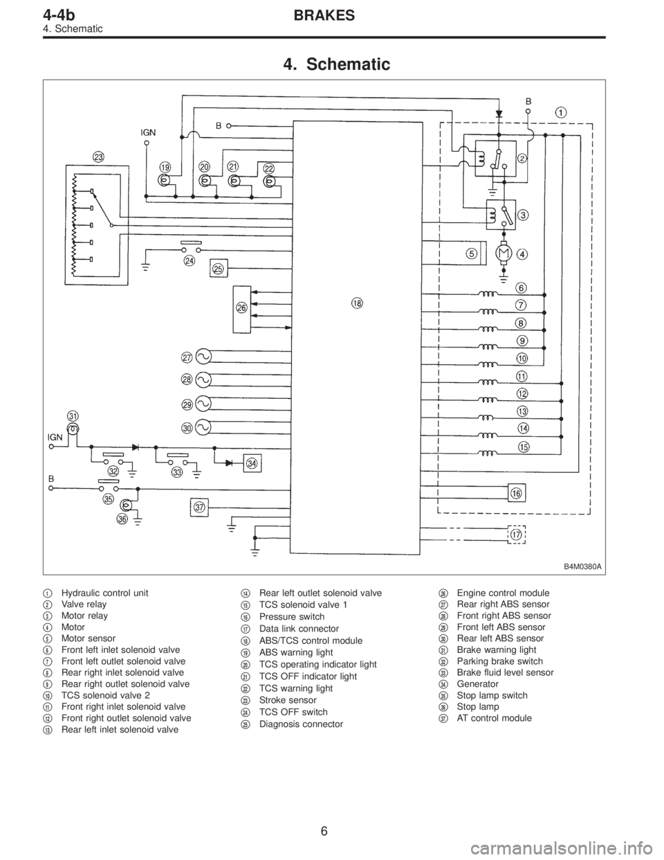
4. Schematic
B4M0380A
�1Hydraulic control unit
�
2Valve relay
�
3Motor relay
�
4Motor
�
5Motor sensor
�
6Front left inlet solenoid valve
�
7Front left outlet solenoid valve
�
8Rear right inlet solenoid valve
�
9Rear right outlet solenoid valve
�
10TCS solenoid valve 2
�
11Front right inlet solenoid valve
�
12Front right outlet solenoid valve
�
13Rear left inlet solenoid valve�
14Rear left outlet solenoid valve
�
15TCS solenoid valve 1
�
16Pressure switch
�
17Data link connector
�
18ABS/TCS control module
�
19ABS warning light
�
20TCS operating indicator light
�
21TCS OFF indicator light
�
22TCS warning light
�
23Stroke sensor
�
24TCS OFF switch
�
25Diagnosis connector�
26Engine control module
�
27Rear right ABS sensor
�
28Front right ABS sensor
�
29Front left ABS sensor
�
30Rear left ABS sensor
�
31Brake warning light
�
32Parking brake switch
�
33Brake fluid level sensor
�
34Generator
�
35Stop lamp switch
�
36Stop lamp
�
37AT control module
6
4-4bBRAKES
4. Schematic
Page 2483 of 3342
Front left wheel P7 1�")
5. Control Module I/O Signal
1. I/O SIGNAL VOLTAGE
Contents Connector No. Terminal No.Input/Output signals
Measured value and measuring conditions
ABS
sensor
(Wheel
speed
sensor)Front left wheel P7 1—11 0.12—1 V (When it is 10 Hz.)
Front right wheel P6 8—16 0.12—1 V (When it is 10 Hz.)
Rear left wheel P6 7—15 0.12—1 V (When it is 10 Hz.)
Rear right wheel P7 2—12 0.12—1 V (When it is 10 Hz.)
Hydraulic
unitSolenoid
valveFront left outlet P4 1—GND
10—14 V when the valve is OFF.
Less than 1.5 V when the valve is ON. Front right outlet P5 3—GND
Rear left outlet P5 8—GND
Rear right outlet P4 3—GND
Front left inlet P4 2—GND
10—14 V when the valve is OFF.
Less than 1.0 V when the valve is ON. Front right inlet P5 2—GND
Rear left inlet P5 7—GND
Rear right inlet P4 4—GND
TCS 1 P4 5—GND
10—14 V when the valve is OFF.
Less than 1.0 V when the valve is ON.
TCS 2 P5 6—GND
Valve power supply P6 6—GND Ignition switch ON, 10—14 V
Valve relay power supply P6 1—GNDLess than 1.2 V when IGN is ON.
10—14 V when the system is down.
Motor relay power supply P6 9—GNDLess than 1.0 V when the motor is ON.
10—14 V when the motor is OFF.
Motor sensor signalsP7 3—GNDCyclic waveform of more than 180 Hz
when the motor across terminals is ON.
Less than 70 Hz when the motor is OFF. P7 13—GND
Pressure switch P7 6—GNDH/L toggle signal with the brake pedal off
(Cycle 14 mS, H: 10—14 V, L: less than
0.7 V). 10—14 V with the brake pedal
depressed.
Pedal
stroke
sensorOutput signals P7 5—GND 0.7—0.9 V with the brake pedal off.
Power supply P7 4—14 5±0.4 V
Stop light
switchSwitch P7 7—GNDLess than 2 V when the stop light is off.
10—12 V when the stop light is on.
Switch test signal P7 18—GNDH/L toggle signal with the brake pedal off
(Cycle 14 mS, H: 10—12 V, L: less than
0.7 V). Less than 2 V with the brake pedal
depressed.
TCS OFF switch P7 16—GNDLess than 2.0 V with the switch pressed
and 10—12 V with it released.
Indicator
lightTCS OFF P6 10—GND
Less than2Vwhenthelight is on and
10—12 V when it is off. TCS operation P6 11—GND
TCS warning P6 3—GND
ABS warning P6 2—GND
7
4-4bBRAKES
5. Control Module I/O Signal
Page 2484 of 3342
P6 14—GNDLess than 0.7 V whe")
Contents Connector No. Terminal No.Input/Output signals
Measured value and measuring conditions
TCS
control
unit ECM
commun-
icationTCS,ECM communication
(torque command)P6 14—GNDLess than 0.7 V when the vehicle stands
still.
TCS,ECM communication
(torque command)P6 5—GNDLess than 5 V when the vehicle stands
still.
TCS,ECM communication
(TCS operates)P6 12—GND4—5.4 V when TCS controls no
operations. Less than 0.7 V when it
controls operations.
ECM,TCS communication
(engine control)P6 4—GNDH/L toggle signal with the accelerator
pedal off (Cycle 20 mS, H: 10—14 V, L:
less than 0.7 V). Less than 2.0 V with the
accelerator pedal depressed. Also when
TCS OFF indicator light comes on by TCS
OFF switch.
ABS operation signal P6 13—GND10—14 V when the ABS control does not
operate still and less than 0.7 V when
ABS operates.
Fluid level sensor P7 20—GNDLess than2VwhenIGNisONand10—
14 V when idling.
Select
monitorData is received. P7 9—GND 4—4.5 V when no data is received.
Data is sent. P7 19—GND 4—4.5 V when no data is sent.
Diagnosis connector P7 8—GND 10—14 V when IGN is ON.
Power
supplyIgnition P5 1—GND 10—14 V when IGN is ON.
Battery P5 4—GND 10—14 V
Grounding
linePower P5 5—body 1Ωor less
Digital P7 15—body 1Ωor less
Power P4 6—body 1Ωor less
8
4-4bBRAKES
5. Control Module I/O Signal