Page 1380 of 3342
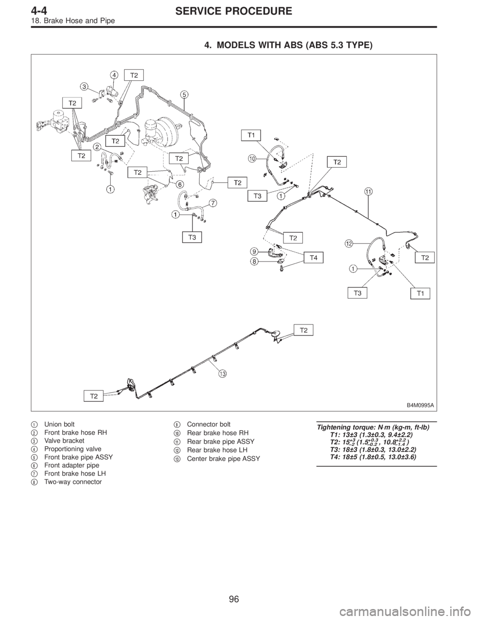
4. MODELS WITH ABS (ABS 5.3 TYPE)
B4M0995A
�1Union bolt
�
2Front brake hose RH
�
3Valve bracket
�
4Proportioning valve
�
5Front brake pipe ASSY
�
6Front adapter pipe
�
7Front brake hose LH
�
8Two-way connector�
9Connector bolt
�
10Rear brake hose RH
�
11Rear brake pipe ASSY
�
12Rear brake hose LH
�
13Center brake pipe ASSY
Tightening torque: N⋅m (kg-m, ft-lb)
T1: 13±3 (1.3±0.3, 9.4±2.2)
T2: 15
+3
�2(1.5+0.3
�0.2, 10.8+2.2
�1.4)
T3: 18±3 (1.8±0.3, 13.0±2.2)
T4: 18±5 (1.8±0.5, 13.0±3.6)
96
4-4SERVICE PROCEDURE
18. Brake Hose and Pipe
Page 1381 of 3342
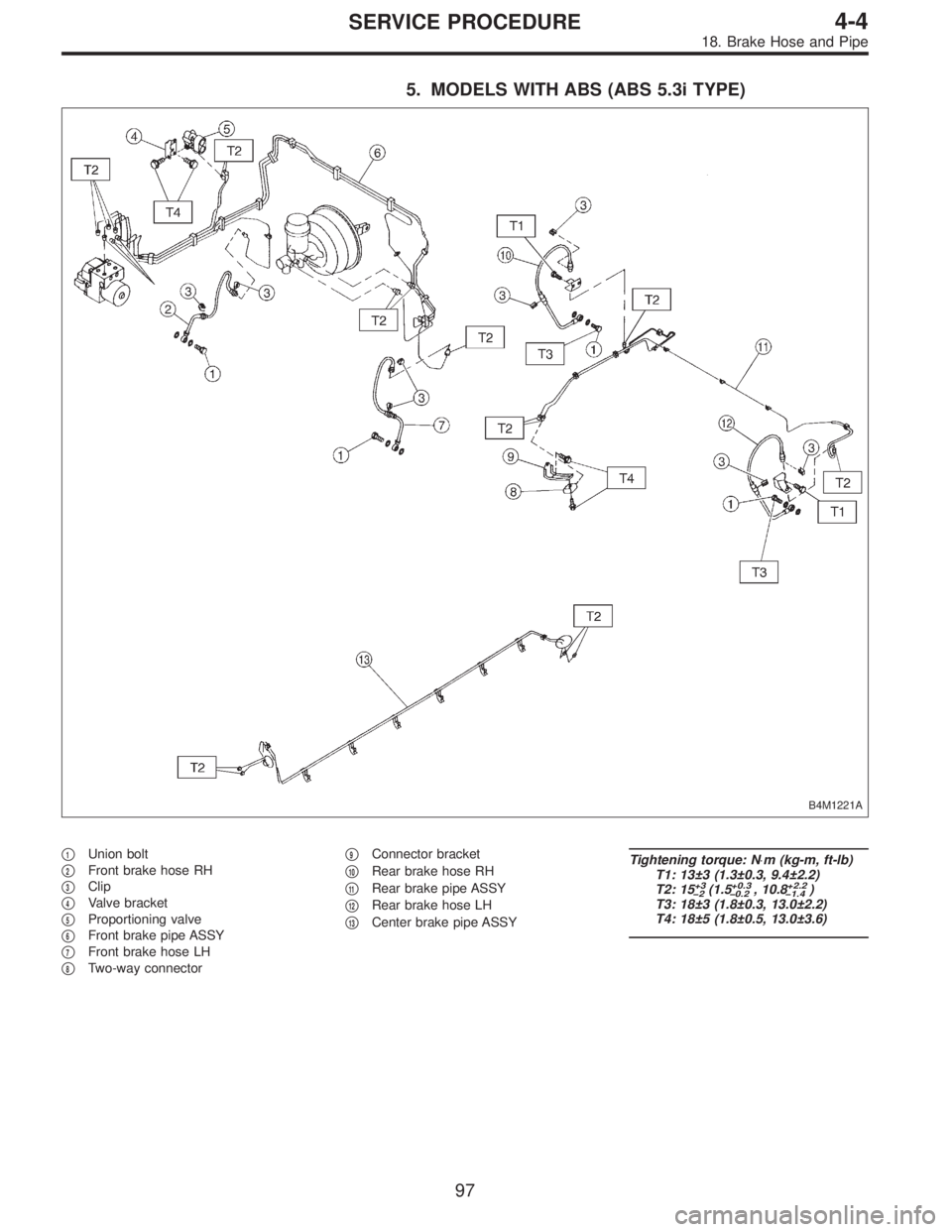
5. MODELS WITH ABS (ABS 5.3i TYPE)
B4M1221A
�1Union bolt
�
2Front brake hose RH
�
3Clip
�
4Valve bracket
�
5Proportioning valve
�
6Front brake pipe ASSY
�
7Front brake hose LH
�
8Two-way connector�
9Connector bracket
�
10Rear brake hose RH
�
11Rear brake pipe ASSY
�
12Rear brake hose LH
�
13Center brake pipe ASSY
Tightening torque: N⋅m (kg-m, ft-lb)
T1: 13±3 (1.3±0.3, 9.4±2.2)
T2: 15
+3
�2(1.5+0.3
�0.2, 10.8+2.2
�1.4)
T3: 18±3 (1.8±0.3, 13.0±2.2)
T4: 18±5 (1.8±0.5, 13.0±3.6)
97
4-4SERVICE PROCEDURE
18. Brake Hose and Pipe
Page 1382 of 3342

A: RULES FOR EFFECTIVE BLEEDING
1) Pressure is not applied to suction pipe by depressing
brake pedal. When any of the following are performed,
bleed air from suction")
19. Air Bleeding (With TCS model)
A: RULES FOR EFFECTIVE BLEEDING
1) Pressure is not applied to suction pipe by depressing
brake pedal. When any of the following are performed,
bleed air from suction pipe by air bleeding control opera-
tion.
NOTE:
For TCS vehicle, suction pipe is installed between master
cylinder and hydraulic unit to allow flow of brake fluid
between them during ABS and TCS operation.
(1) When brake pipe is disconnected from master cyl-
inder.
(2) When brake pipe between hydraulic unit and mas-
ter cylinder is disconnected.
(3) When fluid is emptied from reservoir tank.
2) The time interval between two brake pedal operations
(from the time when the pedal is released to the time when
it is depressed another time) shall be approximately 3 sec-
onds.
3) The air bleeder on each brake shall be released for 1
to 2 seconds.
B: BLEEDING PROCEDURE WITH AIR
BLEEDING CONTROL
1. BLEEDING PROCEDURE
CAUTION:
�The FMVSS No. 116, fresh DOT3 or 4 brake fluid
must be used.
�Cover bleeder with waste cloth, when loosening it,
to prevent brake fluid from being splashed over sur-
rounding parts.
�Avoid mixing different brands of brake fluid to pre-
vent degrading the quality of the fluid.
�Be careful not to allow dirt or dust to get into the
reservoir tank.
�During bleeding operation, keep the brake reserve
tank filled with brake fluid to eliminate entry of air.
NOTE:
�Brake pedal operating must be very slow.
�For convenience and safety, it is advisable to have two
man working.
G4M0434
1) Start air bleeding control operation.
[W19C0] or 4-4 [W19D0].>
2) Make sure that there is no leak from joints and connec-
tions of the brake system.
3) Bleed air through front RH caliper by operating brake
pedal.
(1) Fit one end of vinyl tube into the air bleeder and put
the other end into a brake fluid container.
98
4-4SERVICE PROCEDURE
19. Air Bleeding (With TCS model)
Page 1384 of 3342
 Operate FRO (Front Right Outlet) valve and RLO
(Rear Left Outlet) valve to bleed air from hydraulic unit
outlet circuit.
(1) Press TCS OFF switch while depressing brake
pedal.
(2) Make sure ABS wa")
11) Operate FRO (Front Right Outlet) valve and RLO
(Rear Left Outlet) valve to bleed air from hydraulic unit
outlet circuit.
(1) Press TCS OFF switch while depressing brake
pedal.
(2) Make sure ABS warning light illuminates.
(3) Repeatedly depress and release brake pedal 10
times or more while pressing TCS OFF switch.
NOTE:
�Air comes out from reservoir tank.
12) Operate FLO (Front Left Outlet) valve and RRO (Rear
Right Outlet) valve to bleed air from hydraulic unit outlet
circuit.
(1) Press TCS OFF switch while depressing brake
pedal.
(2) Make sure TCS warning light illuminates.
(3) Repeatedly depress and release brake pedal 10
times or more while pressing TCS OFF switch.
NOTE:
�Air comes out from reservoir tank.
�The operations in steps 11) and 12) above can be
switched with each other by operating brake pedal (stop
light switch) while pressing TCS OFF switch.
�Repeat procedures 11) and 12) until air no longer comes
out of reservoir tank.
13) Perform these steps for the brakes connecting to the
secondary chamber of master cylinder, first, and then for
the ones connecting to primary chamber. With all proce-
dures completed, fully depress the brake pedal and keep
it in that position for approximately 20 seconds to make
sure that there is no leak evident in the entire system.
14) Turn ignition switch OFF.
15) Perform TCS sequence control.
[W20F0].>
100
4-4SERVICE PROCEDURE
19. Air Bleeding (With TCS model)
Page 1385 of 3342
 Check the pedal stroke.
While the engine is idling, depress the brake pedal with a
490 N (50 kg, 110 lb) load and measure the distance
between the brake pedal and steering wheel. With the")
G4M0436
16) Check the pedal stroke.
While the engine is idling, depress the brake pedal with a
490 N (50 kg, 110 lb) load and measure the distance
between the brake pedal and steering wheel. With the
brake pedal released, measure the distance between the
pedal and steering wheel again. The difference between
the two measurements must be less than specified.
Specified pedal stroke:
With TCS
95 mm (3.74 in)
When depressing brake pedal with a 490 N (50 kg,
110 lb) load.
If the distance is more than specifications, there is a
possibility that air is in the brake line. Bleed air from the
brake line.
17) Turn ignition switch OFF.
18) Disconnect select monitor or diagnosis terminal.
19) Add brake fluid to the required level (MAX. level) of
reserve tank.
20) As a final step, test run the vehicle at low speed and
apply brakes relatively hard 2 to 3 times to ensure that
brakes provide normal braking action on all four wheels
without dragging and uneven braking.
2. CONDITIONS FOR AIR BLEEDING CONTROL
Stop light
switchTCS OFF
switchPump
motorTCS
valveFRO
RLOFLO
RROTCS
operating
indicator
lightABS
warning
lightTCS
warning
light
Air
bleeding
control is
operating.OFF ON ON Close Close Close ON ON ON
ON ON OFF Open Open Close ON ON OFF
ON ON OFF Open Close Open ON OFF ON
ON or OFF OFF OFF Open Close Close ON OFF OFF
Stops tem-
porarily.*——OFF Open Close Close OFF OFF OFF
Prohibited.——OFF Open Close Close OFF ON ON
*: When brake fluid level switch detects brake fluid in LOW level, control operation stops temporarily. After refilling brake fluid, operation
re-starts.
101
4-4SERVICE PROCEDURE
19. Air Bleeding (With TCS model)
Page 1386 of 3342

3. CONDITIONS FOR COMPLETION OF AIR
BLEEDING CONTROL
When any of the following conditions occurs, ABS and TCS
warning lights illuminate. Air bleeding control stops, while
the ABS and TCS function will then stop. The brake sys-
tem functions as a conventional brake system.
1) When the speed of at least one wheel reaches 10 km/h
(6 MPH).
2) When terminal No. 4 is separated from diagnosis termi-
nal. (When select monitor is not used.)
3) When pump motor remains ON for two minutes.
4) When TCS valve remains open for two minutes.
5) When outlet valve remains closed for two minutes.
6) When malfunction is detected.
NOTE:
When a malfunction is detected the air bleeding operation
stops and the trouble codes are stored in memory.
B4M0082C
C: AIR BLEEDING CONTROL WITH
DIAGNOSIS CONNECTOR
1) Connect diagnosis terminals to terminal No. 4 of the
diagnosis connector beside driver’s seat heater unit.
B4M0621A
2) Start the engine while pushing TCS OFF switch.
NOTE:
Keep the TCS OFF switch depressed even after the engine
has started.
3) After ABS and TCS warning lights go out, depress
brake pedal within 0.5 seconds.
4) After ensuring TCS ON indicator illuminates, release
TCS OFF switch and brake pedal.
5) Air bleeding control operation starts.
102
4-4SERVICE PROCEDURE
19. Air Bleeding (With TCS model)
Page 1389 of 3342
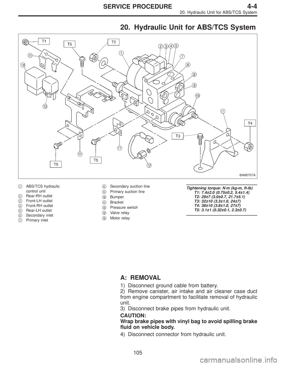
20. Hydraulic Unit for ABS/TCS System
B4M0707A
�1ABS/TCS hydraulic
control unit
�
2Rear-RH outlet
�
3Front-LH outlet
�
4Front-RH outlet
�
5Rear-LH outlet
�
6Secondary inlet
�
7Primary inlet�
8Secondary suction line
�
9Primary suction line
�
10Bumper
�
11Bracket
�
12Pressure switch
�
13Valve relay
�
14Motor relay
Tightening torque: N⋅m (kg-m, ft-lb)
T1: 7.4±2.0 (0.75±0.2, 5.4±1.4)
T2: 29±7 (3.0±0.7, 21.7±5.1)
T3: 32±10 (3.3±1.0, 24±7)
T4: 38±10 (3.8±1.0, 27±7)
T5: 3.1±1 (0.32±0.1, 2.3±0.7)
A: REMOVAL
1) Disconnect ground cable from battery.
2) Remove canister, air intake and air cleaner case duct
from engine compartment to facilitate removal of hydraulic
unit.
3) Disconnect brake pipes from hydraulic unit.
CAUTION:
Wrap brake pipes with vinyl bag to avoid spilling brake
fluid on vehicle body.
4) Disconnect connector from hydraulic unit.
105
4-4SERVICE PROCEDURE
20. Hydraulic Unit for ABS/TCS System
Page 1390 of 3342
 Remove bolts which secure hydraulic unit bracket, and
remove hydraulic unit from engine compartment.
CAUTION:
�Hydraulic unit cannot be disassembled. Do not
attempt to loosen bolts and nuts")
B4M0628
5) Remove bolts which secure hydraulic unit bracket, and
remove hydraulic unit from engine compartment.
CAUTION:
�Hydraulic unit cannot be disassembled. Do not
attempt to loosen bolts and nuts.
�Do not drop or bump hydraulic unit.
�Do not turn the hydraulic unit upside down or place
it on its side.
�Be careful to prevent foreign particles from getting
into hydraulic unit.
�Do not pull harness disconnecting harness connec-
tor.
B: INSPECTION
1) Check connected and fixed condition of connector.
2) Check for discontinuity or short circuits.
Condition Terminal number Standard Diagram Terminal location
Valve relayTurning off
electricity.A—B90Ω
B4M0629AB4M0630
C—F0Ω
C—E
Turning on
electricity between
A and B.
(DC 12 V)C—F
C—E0Ω
Motor relayTurning off
electricity.a—b* 57Ω
B4M0631AB4M0632
c—d
Turning on
electricity between
a and b.
(DC 12 V)c—d0Ω
*: Attach circuit tester positive probe to terminal“a”and its negative probe to terminal“b”and measure the circuit resistance.
106
4-4SERVICE PROCEDURE
20. Hydraulic Unit for ABS/TCS System