Page 1303 of 3342
9. ABS/TCS System
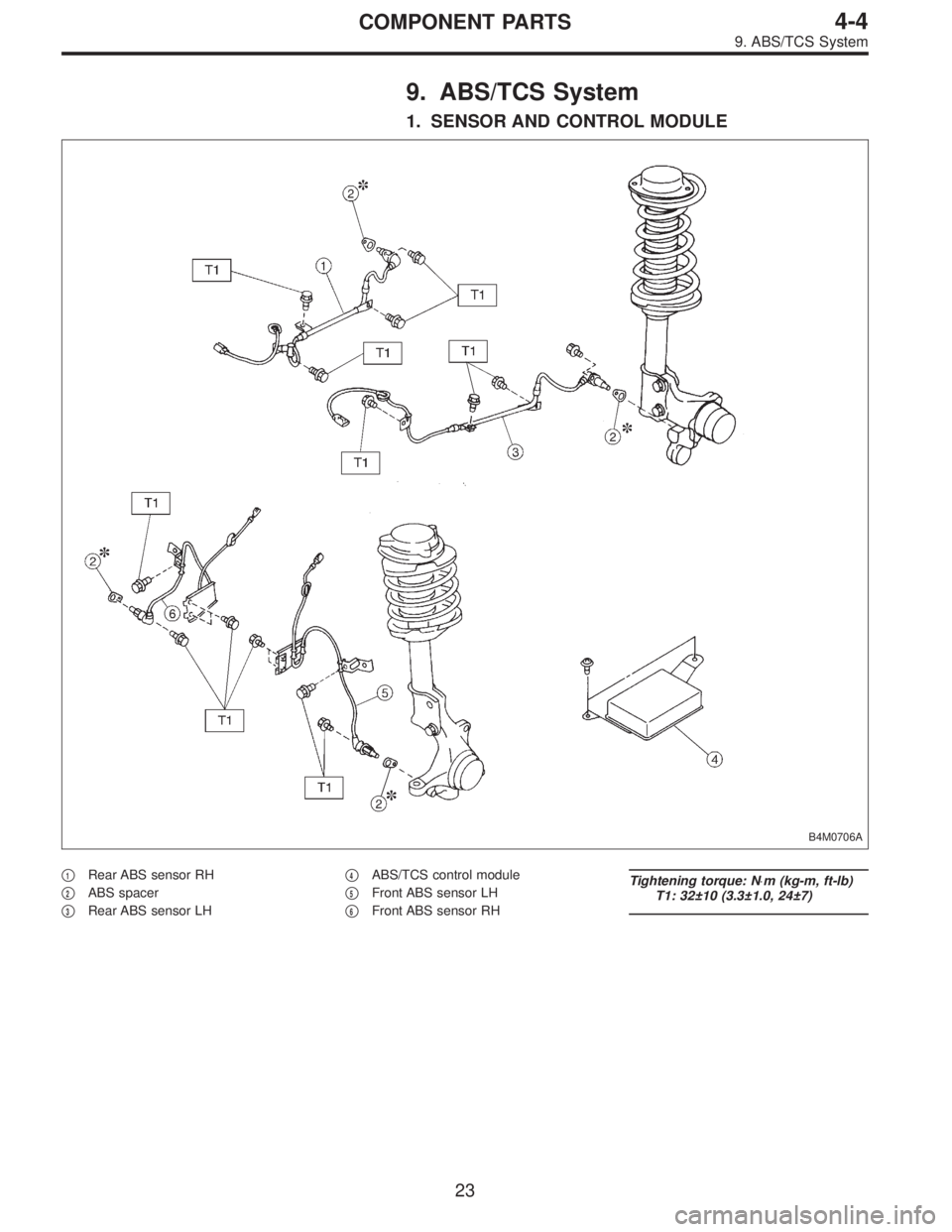
1. SENSOR AND CONTROL MODULE
B4M0706A
�1Rear ABS sensor RH
�
2ABS spacer
�
3Rear ABS sensor LH�
4ABS/TCS control module
�
5Front ABS sensor LH
�
6Front ABS sensor RH
Tightening torque: N⋅m (kg-m, ft-lb)
T1: 32±10 (3.3±1.0, 24±7)
23
4-4COMPONENT PARTS
9. ABS/TCS System
Page 1304 of 3342
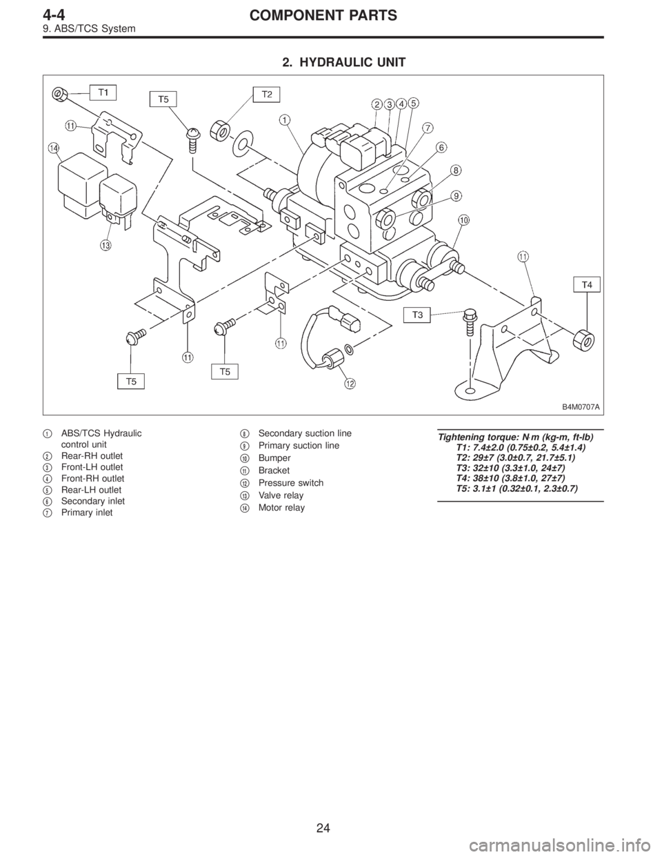
2. HYDRAULIC UNIT
B4M0707A
�1ABS/TCS Hydraulic
control unit
�
2Rear-RH outlet
�
3Front-LH outlet
�
4Front-RH outlet
�
5Rear-LH outlet
�
6Secondary inlet
�
7Primary inlet�
8Secondary suction line
�
9Primary suction line
�
10Bumper
�
11Bracket
�
12Pressure switch
�
13Valve relay
�
14Motor relay
Tightening torque: N⋅m (kg-m, ft-lb)
T1: 7.4±2.0 (0.75±0.2, 5.4±1.4)
T2: 29±7 (3.0±0.7, 21.7±5.1)
T3: 32±10 (3.3±1.0, 24±7)
T4: 38±10 (3.8±1.0, 27±7)
T5: 3.1±1 (0.32±0.1, 2.3±0.7)
24
4-4COMPONENT PARTS
9. ABS/TCS System
Page 1305 of 3342
10. ABS System (ABS 5.3i Type)
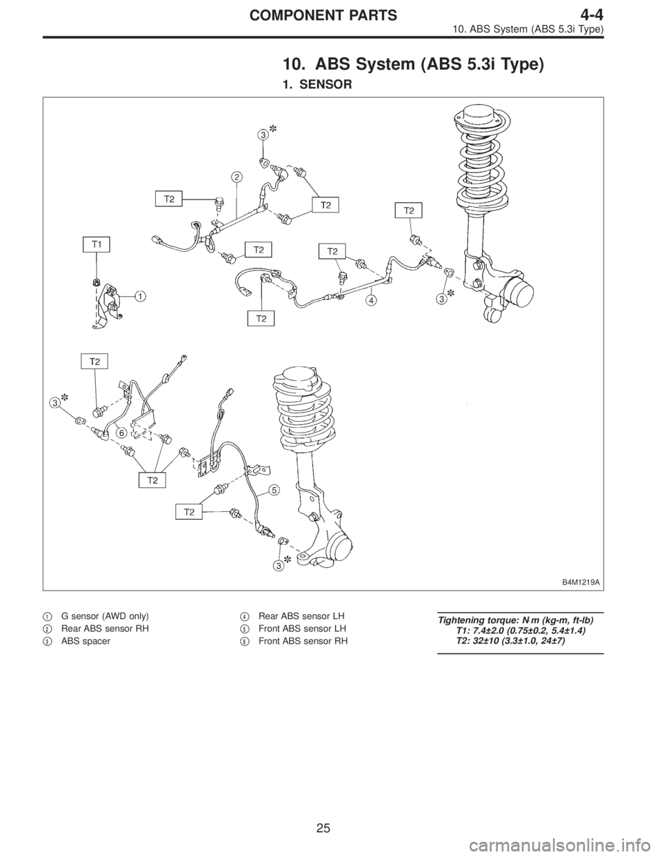
1. SENSOR
B4M1219A
�1G sensor (AWD only)
�
2Rear ABS sensor RH
�
3ABS spacer�
4Rear ABS sensor LH
�
5Front ABS sensor LH
�
6Front ABS sensor RH
Tightening torque: N⋅m (kg-m, ft-lb)
T1: 7.4±2.0 (0.75±0.2, 5.4±1.4)
T2: 32±10 (3.3±1.0, 24±7)
25
4-4COMPONENT PARTS
10. ABS System (ABS 5.3i Type)
Page 1306 of 3342
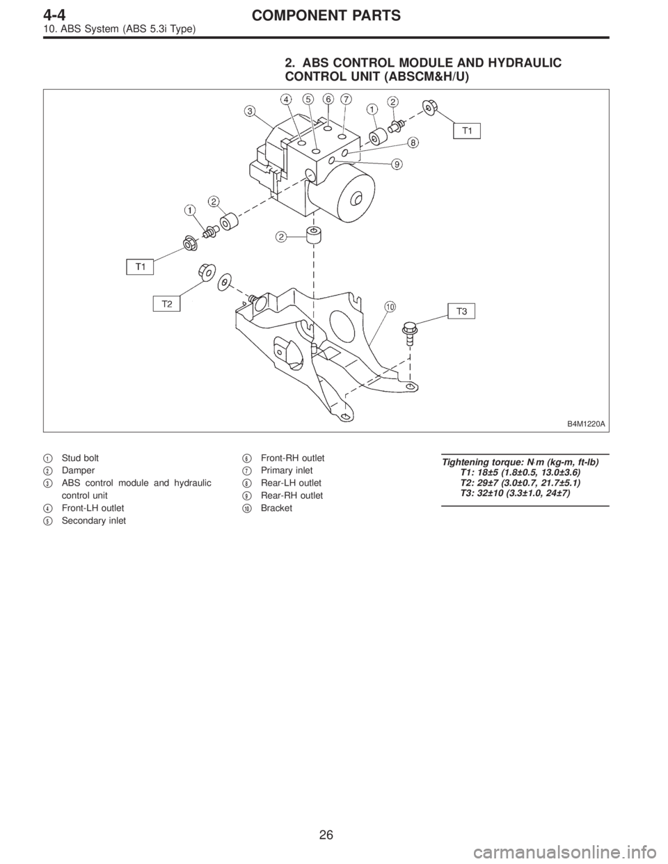
2. ABS CONTROL MODULE AND HYDRAULIC
CONTROL UNIT (ABSCM&H/U)
B4M1220A
�1Stud bolt
�
2Damper
�
3ABS control module and hydraulic
control unit
�
4Front-LH outlet
�
5Secondary inlet�
6Front-RH outlet
�
7Primary inlet
�
8Rear-LH outlet
�
9Rear-RH outlet
�
10Bracket
Tightening torque: N⋅m (kg-m, ft-lb)
T1: 18±5 (1.8±0.5, 13.0±3.6)
T2: 29±7 (3.0±0.7, 21.7±5.1)
T3: 32±10 (3.3±1.0, 24±7)
26
4-4COMPONENT PARTS
10. ABS System (ABS 5.3i Type)
Page 1334 of 3342
 Remove mud and dirt from the surface of brake master
cylinder.
2) Prepare tools necessary for disassembly operation, and
arrange them neatly on work")
B: DISASSEMBLY
1. PRECAUTIONS FOR DISASSEMBLING
1) Remove mud and dirt from the surface of brake master
cylinder.
2) Prepare tools necessary for disassembly operation, and
arrange them neatly on work bench.
3) Clean work bench.
4) Tools for disassembly operation:
�1 Phillips screwdriver
�1 C-ring pliers
G4M0418
2. DISASSEMBLING PROCEDURE
1) Remove reserve tank.
2) Remove supply valve stopper. (only vehicle equipped
with ABS)
3) Remove filter and cylinder pin. (only vehicle equipped
with TCS)
4) Remove C-ring with C-ring pliers pushing in primary
piston slightly.
NOTE:
Piston may jump out from master cylinder.
5) Extract primary piston assembly and secondary piston
assembly.
CAUTION:
�Do not disassemble the piston assembly; otherwise,
the spring set value may be changed.
�Use brake fluid or methanol to wash inside wall of
cylinder, pistons and piston cups. Be careful not to
damage parts when washing. If methanol is used for
washing, do not dip rubber parts, such as piston cups,
in it for more than 30 seconds; otherwise, they may
become swelled.
C: INSPECTION
If any damage, deformation, wear, swelling, rust, and other
faults are found on the primary piston assembly, second-
ary piston assembly, supply valve stopper, or gasket,
replace the faulty part.
CAUTION:
�The primary and secondary pistons must be
replaced as complete assemblies.
�The service limit of the clearance between each pis-
ton and the master cylinder inner dia. is 0.11 mm
(0.0043 in).
�When handling parts, be extremely careful not to
damage or scratch the parts, or let any foreign matter
get on them.
53
4-4SERVICE PROCEDURE
5. Master Cylinder
Page 1340 of 3342

8. LACK OF BOOSTING ACTION CHECK
Turn off engine, and set the vacuum gauge reading at“0”.
Then, check the fluid pressure when brake pedal is
depressed. The pressure must be greater than the stan-
dard value listed below.
Brake pedal force 147 N (15 kg, 33 lb) 294 N (30 kg, 66 lb)
Models without ABS and
TCS785 kPa
(8 kg/cm
2, 114 psi)2,158 kPa
(22 kg/cm2, 313 psi)
Models with ABS and
TCS588 kPa
(6 kg/cm
2, 85 psi)1,667 kPa
(17 kg/cm2, 242 psi)
9. BOOSTING ACTION CHECK
Set the vacuum gauge reading at 66.7 kPa (500 mmHg,
19.69 inHg) by running engine. Then, check the fluid pres-
sure when brake pedal is depressed. The pressure must
be greater than the standard value listed below.
Brake pedal force 147 N (15 kg, 33 lb) 294 N (30 kg, 66 lb)
Models without ABS and
TCS5,492 kPa
(56 kg/cm
2, 796 psi)8,434 kPa
(86 kg/cm2, 1,223 psi)
Models with ABS and
TCS5,394 kPa
(55 kg/cm
2, 782 psi)10,003 kPa
(102 kg/cm2, 1,450
psi)
D: HANDLING PRECAUTIONS
1) Be careful not to drop brake booster. Brake booster
should be discarded if it has been dropped.
2) Use special care when handling operating rod.
If excessive force is applied to operating rod, sufficient to
cause a change in the angle in excess of ±3°, it may result
in damage to the power piston cylinder.
59
4-4SERVICE PROCEDURE
6. Brake Booster
Page 1350 of 3342

5) Perform these steps for the brakes connecting to the
secondary chamber of master cylinder, first, and then for
the ones con")
Air bleeder tightening torque:
8±1 N⋅m (0.8±0.1 kg-m, 5.8±0.7 ft-lb)
5) Perform these steps for the brakes connecting to the
secondary chamber of master cylinder, first, and then for
the ones connecting to primary chamber. With all proce-
dures completed, fully depress the brake pedal and keep
it in that position for approximately 20 seconds to make
sure that there is no leak evident in the entire system.
G4M0436
6) Perform sequence control. (With ABS model)
4-4 [W15C1].>
7) Check the pedal stroke.
While the engine is idling, depress the brake pedal with a
490 N (50 kg, 110 lb) load and measure the distance
between the brake pedal and steering wheel. With the
brake pedal released, measure the distance between the
pedal and steering wheel again. The difference between
the two measurements must be more than specified.
Specified pedal stroke:
Without ABS
90 mm (3.54 in)
With ABS
95 mm (3.74 in)
When depressing brake pedal with a 490 N (50 kg,
110 lb) load.
(1) Models without ABS
If the distance is more than specifications, there is a
possibility that air is in the brake line. Bleed air from the
brake line.
(2) Models with ABS
If the distance is more than specifications, there is a
possibility air is in the inside of the hydraulic unit.
Therefore, air must be bled from the inside of the
hydraulic unit to the brake pipes in accordance with the
bleeding sequence control.
8) Add brake fluid to the required level (MAX. level) of
reserve tank.
9) As a final step, test run the vehicle at low speed and
apply brakes relatively hard 2 to 3 times to ensure that
brakes provide normal braking action on all four wheels
without dragging and uneven braking.
68
4-4SERVICE PROCEDURE
11. Air Bleeding (Without TCS model)
Page 1354 of 3342
14. ABS Sensor
A: REMOVAL
1. FRONT ABS SENSOR
1) Disconnect front ABS sensor connector located in
engine compartment.
B4M0079A
2) Remove bolts which secure sensor harness to strut.
G4M0451
3) Remove bolts which secure sensor harness to body.
G4M0443
4) Remove bolts which secure front ABS sensor to
housing, and remove front ABS sensor.
CAUTION:
�Be careful not to damage pole piece located at tip of
the sensor and teeth faces during removal.
�Do not pull sensor harness during removal.
5) Remove front disc brake caliper and disc rotor from
housing after removing front tire.
6) Remove front drive shaft and housing and hub assem-
bly.
72
4-4SERVICE PROCEDURE
14. ABS Sensor
 Disconnect front ABS sensor connector located in
engine compartment.
B4M0079A
2) Remove bolts which secure sensor harness to strut.
G4M0451
3) Remove b")