Page 215 of 3342
4-4d
[T»B1]
BRAKES
[ABS
5
.3i
TYPE]
11
.
General
Diagnostics
Table
B
:
CHECKING
THE
HYDRAULIC
UNIT
OPERATION
11
B7
PREPARING
THE
BRAKE
TESTER
.
CHECK
;
Is
the
brake
tester
available?
ves
:
CHECKING
THE
HYDRAULIC
UNIT
ABS
OPERA-
TION
WITH
BRAKE
TESTER
<
Ref
.
to
4-4
[W25C2]
.*10
>
nio
:
CHECKING
THE
HYDRAULIC
UNIT
ABS
OPERA-
TION
BY
PRESSURE
GAUGE<
Ref
.
to
4-4
[W25C1
]
.*10
>
210
Page 216 of 3342
6-3
[113soa1
WIRING
DIAGRAM
6
.
Wiring
Diagram
6
.
Wiring
Diagram
4
.
ANTI-LOCK
BRAKE
SYSTEM
CombinationStop
light
To
Power
Supply
Routing
meter
switch
FB-5
SBF-6FB-35FB-22FB-30FB-20
ABS
indicator
FUSE
No
.19
SBF
HOLDER
FUSE
No
.18
FUSE
No
.15
FUSE
k12
FUSE
No
.15
c
:
i14
*
:
With
cruise
control
D
T1
+
:
B65
~~'
B64
i1
B37
w
----------------
r----------
--
--
-----------
F73
(Black)
B65
(Black)
F49
B64
12
456789107112131415
1
4
1
16
1
17
1
118
1
1
21
20
1
21
1
22
[
23242526
U7
1
28
1
29
1
30
13
11
1
i14
i2
1
4
M_
8510
1
456
89
1
10
1
111
1
1
21
1
~
111
1
1415161
119202122
BU82-04A
2
ABS
control
module
and
hydraulic
control
module
Page 217 of 3342
WIRING
DIAGRAM
[osoa1
6-3
6
.
Wiring
Diagram
F2
100
Twisted
wire
LL
7
-
---
-
---------
-
FtP1
Transmission
control
module
Check
Data
link
connectorconnector
879
EEE
878
a
B56
:c
Ref
.
to
Engine
electrical
system
.
881
Diagnosis
PEterminal
B82
Q1
-
Diagnosis
connector
Front
~--~~
ABS
sensorLH
II
---------------
------_-----_--_----_J
Twisted
wire
ABS
G
sensor
86
B15
P8
(Outback
model
:
Brown)
O
(Other
models
:
Gray)
(Other
models)
(Outback
model)
(Gray)
86
Front
m--F-I
ABS
sensor
RH
n
(Outback
(Other
(Outback
(Other
model)
models)
model)
models)
RearABS
Rear
ABS
sensor
RH
sensor
LH
------------------
P11
1
01
P-am
B78
(Yellow)
879
(Gray)
F1
856
(Black)
1
4
1
4
56
10131
1
1
12131
45
6
8
10
56
88
99
10
111
1314
45678
1
11
1
12
1
13
1
14
1
15
1
16
11
/1
16
1
19
12U]
B82
(Black)
1
456
8100
(Blue)
4
6
171619
111
1
1415161
18192010BU82-04B
3
Page 587 of 3342
 Broken, worn or unlubrica")
Condition Possible cause and testing Corrective action
4. Noisy
clutchExamine whether the noise is generated when the clutch is disengaged, engaged, or partially engaged.
(a) Broken, worn or unlubricated release bearing Replace release bearing.
(b) Insufficient lubrication of pilot bearing Apply grease.
(c) Loose clutch disc hub Replace clutch disc.
(d) Loose torsion spring retainer Replace clutch disc.
(e) Deteriorated or broken torsion spring Replace clutch disc.
5. Clutch
grabs.When starting the vehicle with the clutch partially engaged, the clutch engages suddenly and the vehicle jumps
instead of making a smooth start.
(a) Grease or oil on facing Replace clutch disc.
(b) Deteriorated cushioning spring Replace clutch disc.
(c) Worn or rusted spline of clutch disc or mainTake off rust, apply grease or replace clutch shaft disc or
mainshaft.
(d) Deteriorated or broken torsion spring Replace clutch disc.
(e) Loose engine mounting Retighten or replace mounting.
(f ) Deteriorated diaphragm spring Replace.
20
2-10DIAGNOSTICS
1. Clutch System
Page 1264 of 3342
 Feed")
9. Power Steering Fluid
A: RECOMMENDED AIR BLEEDING AND
POWER STEERING FLUID
Recommended power steering fluid Manufacturer
ATF DEXRON II or ATF DEXRON IIEB.P.
CALTEX
CASTROL
MOBIL
SHELL
TEXACO
1) Feed the specified fluid with its level being about 5 cm
(2.0 in) lower than the mouth of tank.
2) Continue to turn steering wheel slowly from lock to lock
until bubbles stop appearing in the tank while keeping the
fluid at that level.
3) In case air is absorbed to deliver bubbles into piping
because the fluid level is lower, leave it about half an hour
and then do the step 2) all over again.
4) Start, and idle the engine.
5) Continue to turn steering wheel slowly from lock to lock
again until bubbles stop appearing in the tank while keep-
ing the fluid at that level.
It is normal that bubbles stop appearing after three times
turning of steering wheel.
6) In case bubbles do not stop appearing in the tank, leave
it about half an hour and then do the step 5) all over again.
7) Stop the engine, and take out safety stands after jack-
ing up vehicle again.
Then lower the vehicle, and idle the engine.
8) Continue to turn steering wheel from lock to lock until
bubbles stop appearing and change of the fluid level is
within 3 mm (0.12 in).
9) In case the following happens, leave it about half an
hour and then do step 8) again.
(1) The fluid level changes over 3 mm (0.12 in).
(2) Bubbles remain on the upper surface of the fluid.
(3) Grinding noise is generated from oil pump.
10) Check the fluid leakage at flare nuts after turning
steering wheel from lock to lock with engine running.
CAUTION:
�Before checking, wipe off any fluid on flare nuts and
piping.
�In case the fluid leaks from flare nut, it is caused by
dust (or the like) and/or damage between flare and
tapered seat in piping.
�So remove the flare nut, tighten again it to the speci-
fied torque after cleaning flare and tapered seat. If flare
or tapered seat is damaged, replace it with a new one.
11) Inspect fluid level on flat and level surface with engine
“OFF”by indicator of filler cap.
80
4-3SERVICE PROCEDURE
9. Power Steering Fluid
Page 1283 of 3342
1. Brakes
A: SPECIFICATIONS
1. MODELS WITH ABS OR ABS/TCS
Model Sedan Wagon
Engine (cc) 2200 2200
Driving system FWD AWD FWD AWD
LLLSLLLS
Front
brakeType Disc (Floating type, ventilated)
Effective disc diameter
mm (in)210 (8.27)
Disc thickness x Outer diameter
mm (in)24 x 260 (0.94 x 10.24)
Effective cylinder diameter
mm (in)57.2 (2.252)
Pad dimensions
(length x width x thickness)
mm (in)112.4 x 44.3 x 11.0 (4.43 x 1.744 x 0.433)
Clearance adjustment Automatic adjustment
Rear
brakeType Disc (Floating type)
Effective disc diameter
mm (in)230 (9.06)
Disc thickness x Outer diameter
mm (in)10 x 266 (0.39 x 10.47)
Effective cylinder diameter
mm (in)34.9 (1.374) 38.1 (1.500)
Pad dimensions
(length x width x thickness)
mm (in)92.4 x 33.7 x 10.0 (3.638 x 1.327 x 0.394)
Clearance adjustment Automatic adjustment
3
4-4SPECIFICATIONS AND SERVICE DATA
1. Brakes
Page 1284 of 3342
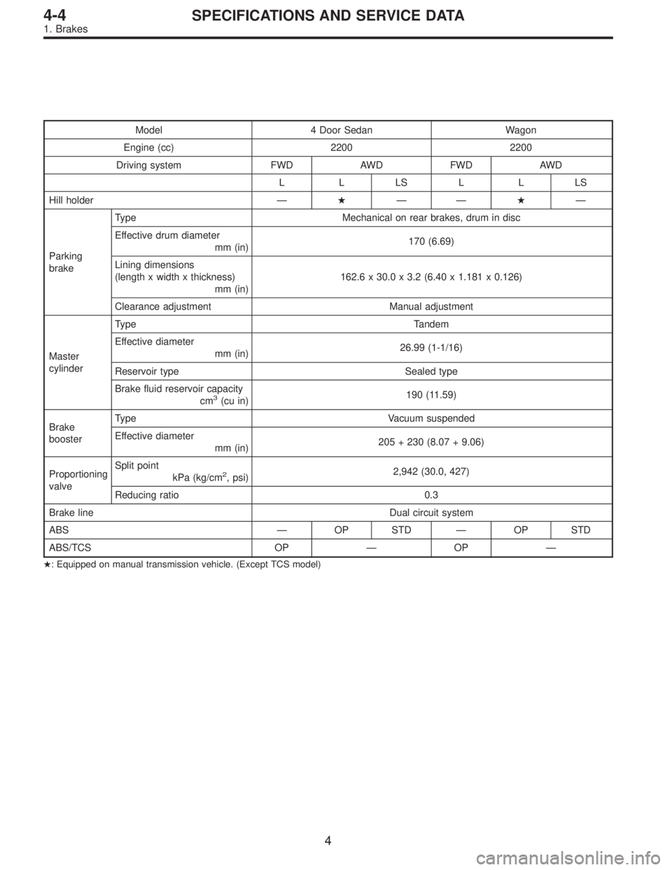
Model 4 Door Sedan Wagon
Engine (cc) 2200 2200
Driving system FWD AWD FWD AWD
LLLSLLLS
Hill holder—�——�—
Parking
brakeType Mechanical on rear brakes, drum in disc
Effective drum diameter
mm (in)170 (6.69)
Lining dimensions
(length x width x thickness)
mm (in)162.6 x 30.0 x 3.2 (6.40 x 1.181 x 0.126)
Clearance adjustment Manual adjustment
Master
cylinderType Tandem
Effective diameter
mm (in)26.99 (1-1/16)
Reservoir type Sealed type
Brake fluid reservoir capacity
cm
3(cu in)190 (11.59)
Brake
boosterType Vacuum suspended
Effective diameter
mm (in)205 + 230 (8.07 + 9.06)
Proportioning
valveSplit point
kPa (kg/cm
2, psi)2,942 (30.0, 427)
Reducing ratio 0.3
Brake line Dual circuit system
ABS—OP STD—OP STD
ABS/TCS OP—OP—
�: Equipped on manual transmission vehicle. (Except TCS model)
4
4-4SPECIFICATIONS AND SERVICE DATA
1. Brakes
Page 1285 of 3342
2. MODELS WITHOUT ABS OR ABS/TCS
Model Sedan Wagon
Engine (cc) 2200
Driving system FWD AWD FWD AWD
L L L POST BRIGHTON L
Front
brakeType Disc (Floating type, ventilated)
Effective disc diameter
mm (in)210 (8.27)
Disc thickness x Outer diameter
mm (in)24 x 260 (0.94 x 10.24)
Effective cylinder diameter
mm (in)57.2 (2.252)
Pad dimensions
(length x width x thickness)
mm (in)112.4 x 44.3 x 11.0 (4.43 x 1.744 x 0.433)
Clearance adjustment Automatic adjustment
Rear
brakeType Drum (Leading-Trailing type)
Effective drum diameter
mm (in)228.6 (9)
Effective cylinder diameter
mm (in)17.4 (0.685) 19.0 (0.748)
Lining dimensions
(length x width x thickness)
mm (in)218.8 x 35.0 x 4.1 (8.61 x 1.378 x 0.161)
Clearance adjustment Automatic adjustment
5
4-4SPECIFICATIONS AND SERVICE DATA
1. Brakes
![SUBARU LEGACY 1997 Service Repair Manual
4-4d
[T»B1]
BRAKES
[ABS
5
.3i
TYPE]
11
.
General
Diagnostics
Table
B
:
CHECKING
THE
HYDRAULIC
UNIT
OPERATION
11
B7
PREPARING
THE
BRAKE
TESTER
.
CHECK
;
Is
the
brake
tester
available?
ves
:
CHE](/manual-img/17/57434/w960_57434-214.png "SUBARU LEGACY 1997 Service Repair Manual
4-4d
[T»B1]
BRAKES
[ABS
5
.3i
TYPE]
11
.
General
Diagnostics
Table
B
:
CHECKING
THE
HYDRAULIC
UNIT
OPERATION
11
B7
PREPARING
THE
BRAKE
TESTER
.
CHECK
;
Is
the
brake
tester
available?
ves
:
CHE")


 2200 2200
Driving system FWD AWD FWD AWD
LLLSLLLS
Front
brakeType Disc (Floating type, ventilated)
Effective dis")
 2200
Driving system FWD AWD FWD AWD
L L L POST BRIGHTON L
Front
brakeType Disc (Floating type, ventilated)
Effective disc diameter
mm (in")