1997 SSANGYONG KORANDO manual transmission
[x] Cancel search: manual transmissionPage 1139 of 2053
5A-44 AUTOMATIC TRANSMISSION
SSANGYONG MY2002
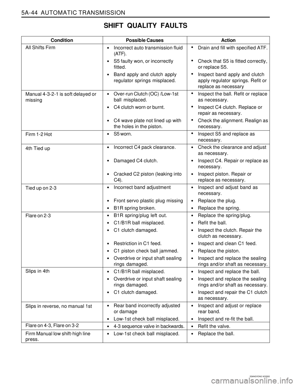
SHIFT QUALITY FAULTS
Condition Possible Causes
Incorrect auto transmission fluid
(ATF).
S5 faulty won, or incorrectly
fitted.
Band apply and clutch apply
regulator springs misplaced.
Over-run Clutch (OC) /Low-1st
ball misplaced.
C4 clutch worn or burnt.
C4 wave plate not lined up with
the holes in the piston.
S5 worn.
Incorrect C4 pack clearance.
Damaged C4 clutch.
Cracked C2 piston (leaking into
C4).
Incorrect band adjustment
Front servo plastic plug missing
B1R spring broken.
B1R spring/plug left out.
C1/B1R ball misplaced.
C1 clutch damaged.
Restriction in C1 feed.
C1 piston check ball jammed.
Overdrive or input shaft sealing
rings damaged.
C1/B1R ball misplaced.
Overdrive or input shaft sealing
rings damaged.
C1 clutch damaged.
Rear band incorrectly adjusted
or damage
Low-1st check ball misplaced.
4-3 sequence valve in backwards.
Low-1st check ball misplaced.Action
Drain and fill with specified ATF.
Check that S5 is fitted correctly,
or replace S5.
Inspect band apply and clutch
apply regulator springs. Refit or
replace as necessary
Inspect the ball. Refit or replace
as necessary.
Inspect C4 clutch. Replace or
repair as necessary.
Check the alignment. Realign as
necessary.
Inspect S5 and replace as
necessary.
Check the clearance and adjust
as necessary.
Inspect C4. Repair or replace as
necessary.
Inspect piston. Repair or
replace as necessary.
Inspect and adjust band as
necessary.
Replace the plug.
Replace the spring.
Replace the spring/plug.
Refit the ball.
Inspect the clutch. Repair the
clutch as necessary.
Inspect and clean C1 feed.
Replace the piston.
Inspect and replace the sealing
rings and/or shaft as necessary.
Inspect and replace the ball.
Inspect and replace the sealing
rings and/or shaft as necessary.
Inspect and repair the C1 clutch
as necessary.
Inspect and adjust or replace
rear band.
Inspect and re-fit the ball.
Refit the valve.
Replace the ball.
Manual 4-3-2-1 is soft delayed or
missing
Firm 1-2 Hot
4th Tied up
Tied up on 2-3
Flare on 2-3
Slips in 4th
Flare on 4-3, Flare on 3-2
Firm Manual low shift-high line
press.
Slips in reverse, no manual 1st
All Shifts Firm
Page 1141 of 2053
5A-46 AUTOMATIC TRANSMISSION
SSANGYONG MY2002
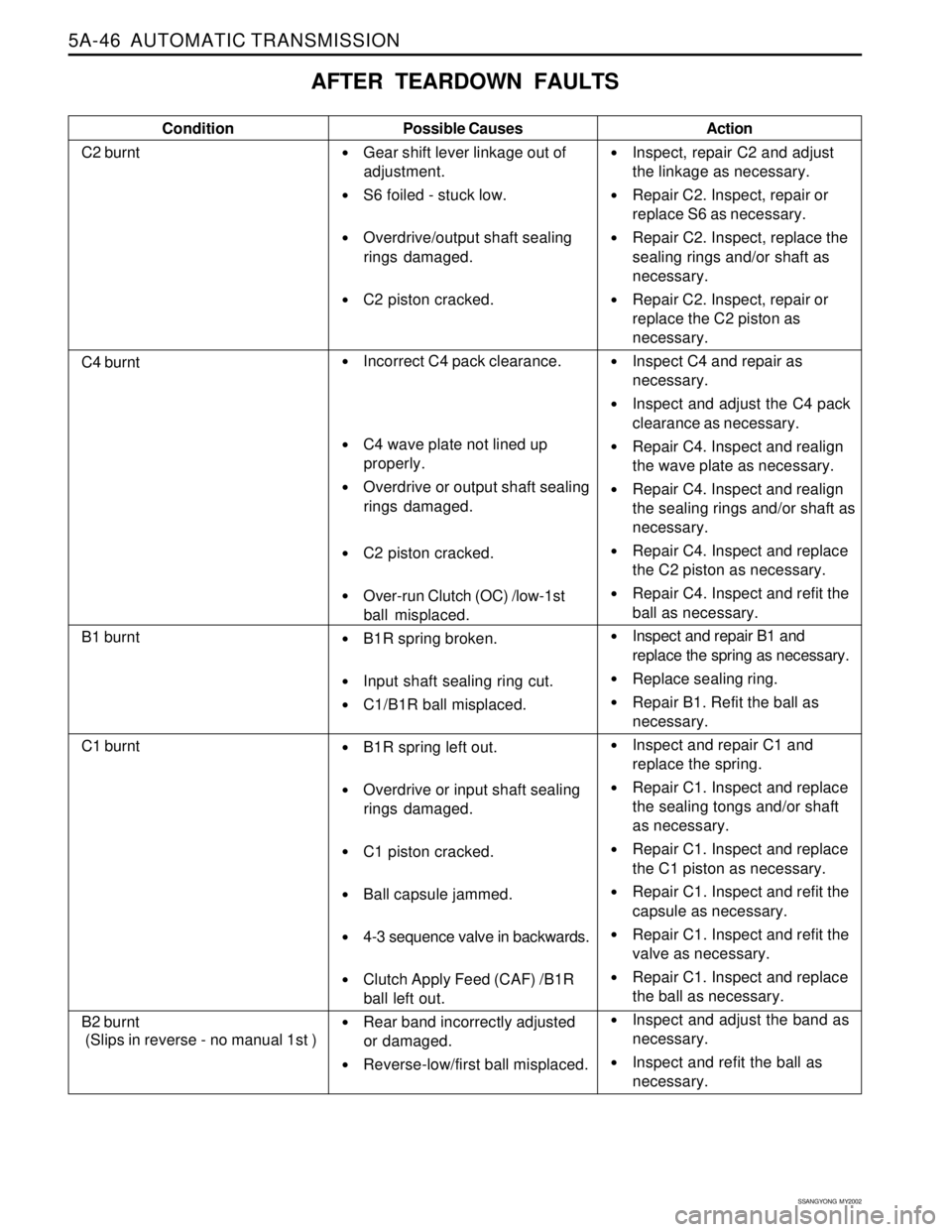
AFTER TEARDOWN FAULTS
Condition
C2 burntPossible Causes
Gear shift lever linkage out of
adjustment.
S6 foiled - stuck low.
Overdrive/output shaft sealing
rings damaged.
C2 piston cracked.
Incorrect C4 pack clearance.
C4 wave plate not lined up
properly.
Overdrive or output shaft sealing
rings damaged.
C2 piston cracked.
Over-run Clutch (OC) /low-1st
ball misplaced.
B1R spring broken.
Input shaft sealing ring cut.
C1/B1R ball misplaced.
B1R spring left out.
Overdrive or input shaft sealing
rings damaged.
C1 piston cracked.
Ball capsule jammed.
4-3 sequence valve in backwards.
Clutch Apply Feed (CAF) /B1R
ball left out.
Rear band incorrectly adjusted
or damaged.
Reverse-low/first ball misplaced.Action
Inspect, repair C2 and adjust
the linkage as necessary.
Repair C2. Inspect, repair or
replace S6 as necessary.
Repair C2. Inspect, replace the
sealing rings and/or shaft as
necessary.
Repair C2. Inspect, repair or
replace the C2 piston as
necessary.
Inspect C4 and repair as
necessary.
Inspect and adjust the C4 pack
clearance as necessary.
Repair C4. Inspect and realign
the wave plate as necessary.
Repair C4. Inspect and realign
the sealing rings and/or shaft as
necessary.
Repair C4. Inspect and replace
the C2 piston as necessary.
Repair C4. Inspect and refit the
ball as necessary.
Inspect and repair B1 and
replace the spring as necessary.
Replace sealing ring.
Repair B1. Refit the ball as
necessary.
Inspect and repair C1 and
replace the spring.
Repair C1. Inspect and replace
the sealing tongs and/or shaft
as necessary.
Repair C1. Inspect and replace
the C1 piston as necessary.
Repair C1. Inspect and refit the
capsule as necessary.
Repair C1. Inspect and refit the
valve as necessary.
Repair C1. Inspect and replace
the ball as necessary.
Inspect and adjust the band as
necessary.
Inspect and refit the ball as
necessary.
C4 burnt
B1 burnt
C1 burnt
B2 burnt
(Slips in reverse - no manual 1st )
Page 1153 of 2053
5A-58 AUTOMATIC TRANSMISSION
SSANGYONG MY2002
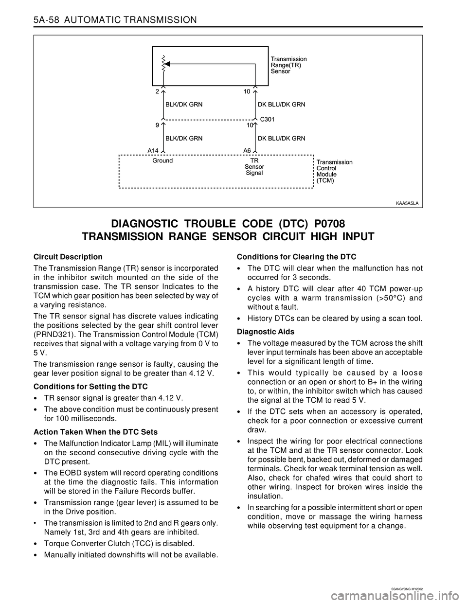
Circuit Description
The Transmission Range (TR) sensor is incorporated
in the inhibitor switch mounted on the side of the
transmission case. The TR sensor Indicates to the
TCM which gear position has been selected by way of
a varying resistance.
The TR sensor signal has discrete values indicating
the positions selected by the gear shift control lever
(PRND321). The Transmission Control Module (TCM)
receives that signal with a voltage varying from 0 V to
5 V.
The transmission range sensor is faulty, causing the
gear lever position signal to be greater than 4.12 V.
Conditions for Setting the DTC
TR sensor signal is greater than 4.12 V.
The above condition must be continuously present
for 100 milliseconds.
Action Taken When the DTC Sets
The Malfunction Indicator Lamp (MIL) will illuminate
on the second consecutive driving cycle with the
DTC present.
The EOBD system will record operating conditions
at the time the diagnostic fails. This information
will be stored in the Failure Records buffer.
Transmission range (gear lever) is assumed to be
in the Drive position.
The transmission is limited to 2nd and R gears only.
Namely 1st, 3rd and 4th gears are inhibited.
Torque Converter Clutch (TCC) is disabled.
Manually initiated downshifts will not be available.
DIAGNOSTIC TROUBLE CODE (DTC) P0708
TRANSMISSION RANGE SENSOR CIRCUIT HIGH INPUT
Conditions for Clearing the DTC
The DTC will clear when the malfunction has not
occurred for 3 seconds.
A history DTC will clear after 40 TCM power-up
cycles with a warm transmission (>50°C) and
without a fault.
History DTCs can be cleared by using a scan tool.
Diagnostic Aids
The voltage measured by the TCM across the shift
lever input terminals has been above an acceptable
level for a significant length of time.
This would typically be caused by a loose
connection or an open or short to B+ in the wiring
to, or within, the inhibitor switch which has caused
the signal at the TCM to read 5 V.
If the DTC sets when an accessory is operated,
check for a poor connection or excessive current
draw.
Inspect the wiring for poor electrical connections
at the TCM and at the TR sensor connector. Look
for possible bent, backed out, deformed or damaged
terminals. Check for weak terminal tension as well.
Also, check for chafed wires that could short to
other wiring. Inspect for broken wires inside the
insulation.
In searching for a possible intermittent short or open
condition, move or massage the wiring harness
while observing test equipment for a change.
KAA5A5LA
Page 1167 of 2053
5A-72 AUTOMATIC TRANSMISSION
SSANGYONG MY2002
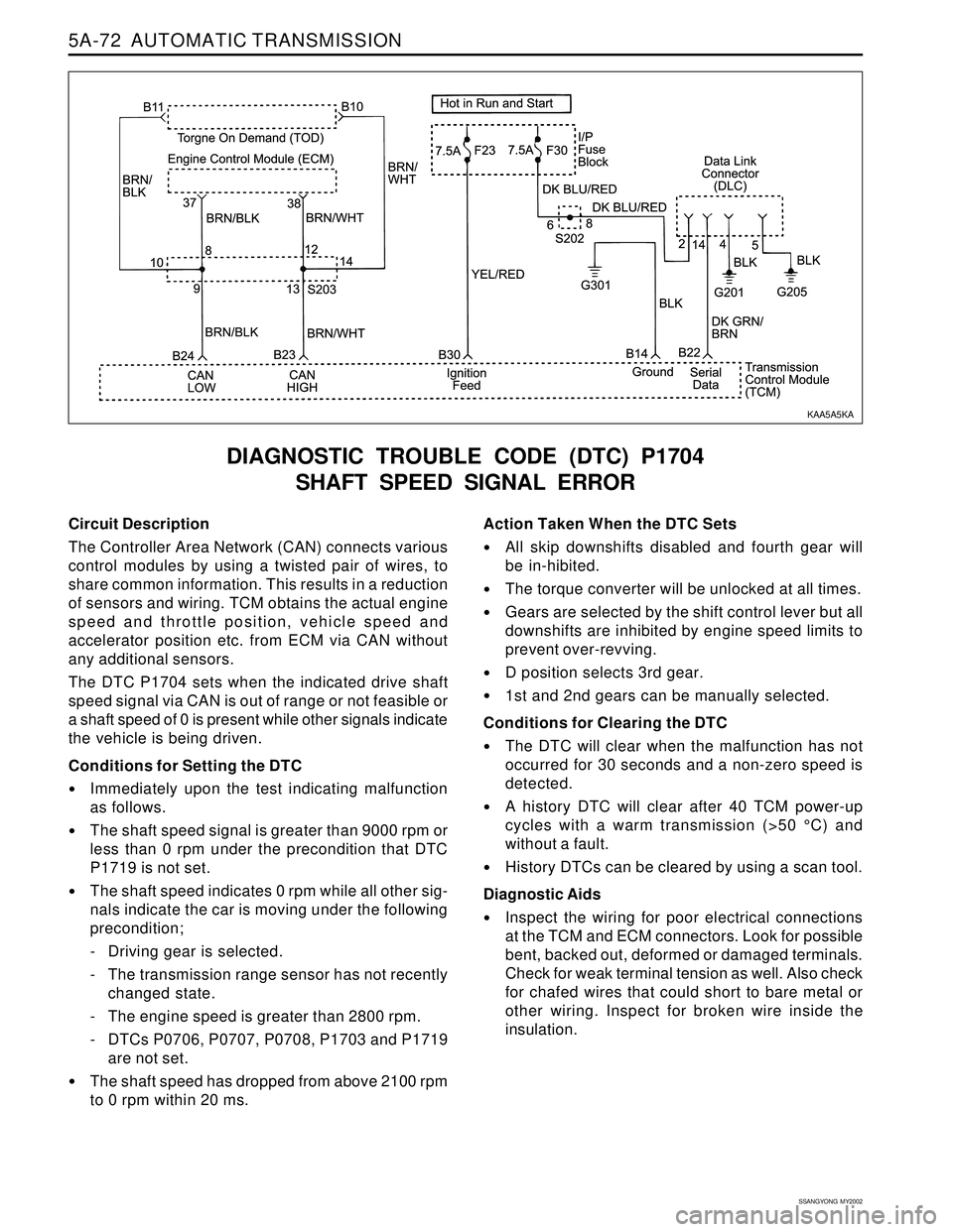
Circuit Description
The Controller Area Network (CAN) connects various
control modules by using a twisted pair of wires, to
share common information. This results in a reduction
of sensors and wiring. TCM obtains the actual engine
speed and throttle position, vehicle speed and
accelerator position etc. from ECM via CAN without
any additional sensors.
The DTC P1704 sets when the indicated drive shaft
speed signal via CAN is out of range or not feasible or
a shaft speed of 0 is present while other signals indicate
the vehicle is being driven.
Conditions for Setting the DTC
Immediately upon the test indicating malfunction
as follows.
The shaft speed signal is greater than 9000 rpm or
less than 0 rpm under the precondition that DTC
P1719 is not set.
The shaft speed indicates 0 rpm while all other sig-
nals indicate the car is moving under the following
precondition;
- Driving gear is selected.
- The transmission range sensor has not recently
changed state.
- The engine speed is greater than 2800 rpm.
- DTCs P0706, P0707, P0708, P1703 and P1719
are not set.
The shaft speed has dropped from above 2100 rpm
to 0 rpm within 20 ms.
DIAGNOSTIC TROUBLE CODE (DTC) P1704
SHAFT SPEED SIGNAL ERROR
Action Taken When the DTC Sets
All skip downshifts disabled and fourth gear will
be in-hibited.
The torque converter will be unlocked at all times.
Gears are selected by the shift control lever but all
downshifts are inhibited by engine speed limits to
prevent over-revving.
D position selects 3rd gear.
1st and 2nd gears can be manually selected.
Conditions for Clearing the DTC
The DTC will clear when the malfunction has not
occurred for 30 seconds and a non-zero speed is
detected.
A history DTC will clear after 40 TCM power-up
cycles with a warm transmission (>50 °C) and
without a fault.
History DTCs can be cleared by using a scan tool.
Diagnostic Aids
Inspect the wiring for poor electrical connections
at the TCM and ECM connectors. Look for possible
bent, backed out, deformed or damaged terminals.
Check for weak terminal tension as well. Also check
for chafed wires that could short to bare metal or
other wiring. Inspect for broken wire inside the
insulation.
KAA5A5KA
Page 1193 of 2053
5A-98 AUTOMATIC TRANSMISSION
SSANGYONG MY2002
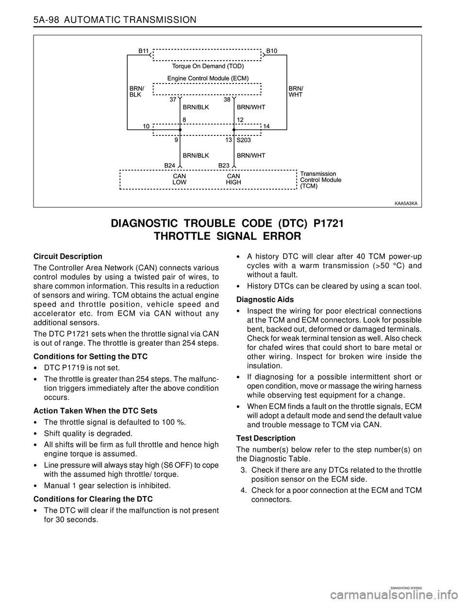
Circuit Description
The Controller Area Network (CAN) connects various
control modules by using a twisted pair of wires, to
share common information. This results in a reduction
of sensors and wiring. TCM obtains the actual engine
speed and throttle position, vehicle speed and
accelerator etc. from ECM via CAN without any
additional sensors.
The DTC P1721 sets when the throttle signal via CAN
is out of range. The throttle is greater than 254 steps.
Conditions for Setting the DTC
DTC P1719 is not set.
The throttle is greater than 254 steps. The malfunc-
tion triggers immediately after the above condition
occurs.
Action Taken When the DTC Sets
The throttle signal is defaulted to 100 %.
Shift quality is degraded.
All shifts will be firm as full throttle and hence high
engine torque is assumed.
Line pressure will always stay high (S6 OFF) to cope
with the assumed high throttle/ torque.
Manual 1 gear selection is inhibited.
Conditions for Clearing the DTC
The DTC will clear if the malfunction is not present
for 30 seconds.
DIAGNOSTIC TROUBLE CODE (DTC) P1721
THROTTLE SIGNAL ERROR
A history DTC will clear after 40 TCM power-up
cycles with a warm transmission (>50 °C) and
without a fault.
History DTCs can be cleared by using a scan tool.
Diagnostic Aids
Inspect the wiring for poor electrical connections
at the TCM and ECM connectors. Look for possible
bent, backed out, deformed or damaged terminals.
Check for weak terminal tension as well. Also check
for chafed wires that could short to bare metal or
other wiring. Inspect for broken wire inside the
insulation.
If diagnosing for a possible intermittent short or
open condition, move or massage the wiring harness
while observing test equipment for a change.
When ECM finds a fault on the throttle signals, ECM
will adopt a default mode and send the default value
and trouble message to TCM via CAN.
Test Description
The number(s) below refer to the step number(s) on
the Diagnostic Table.
3. Check if there are any DTCs related to the throttle
position sensor on the ECM side.
4. Check for a poor connection at the ECM and TCM
connectors.
KAA5A3KA
Page 1209 of 2053
5A-114 AUTOMATIC TRANSMISSION
SSANGYONG MY2002
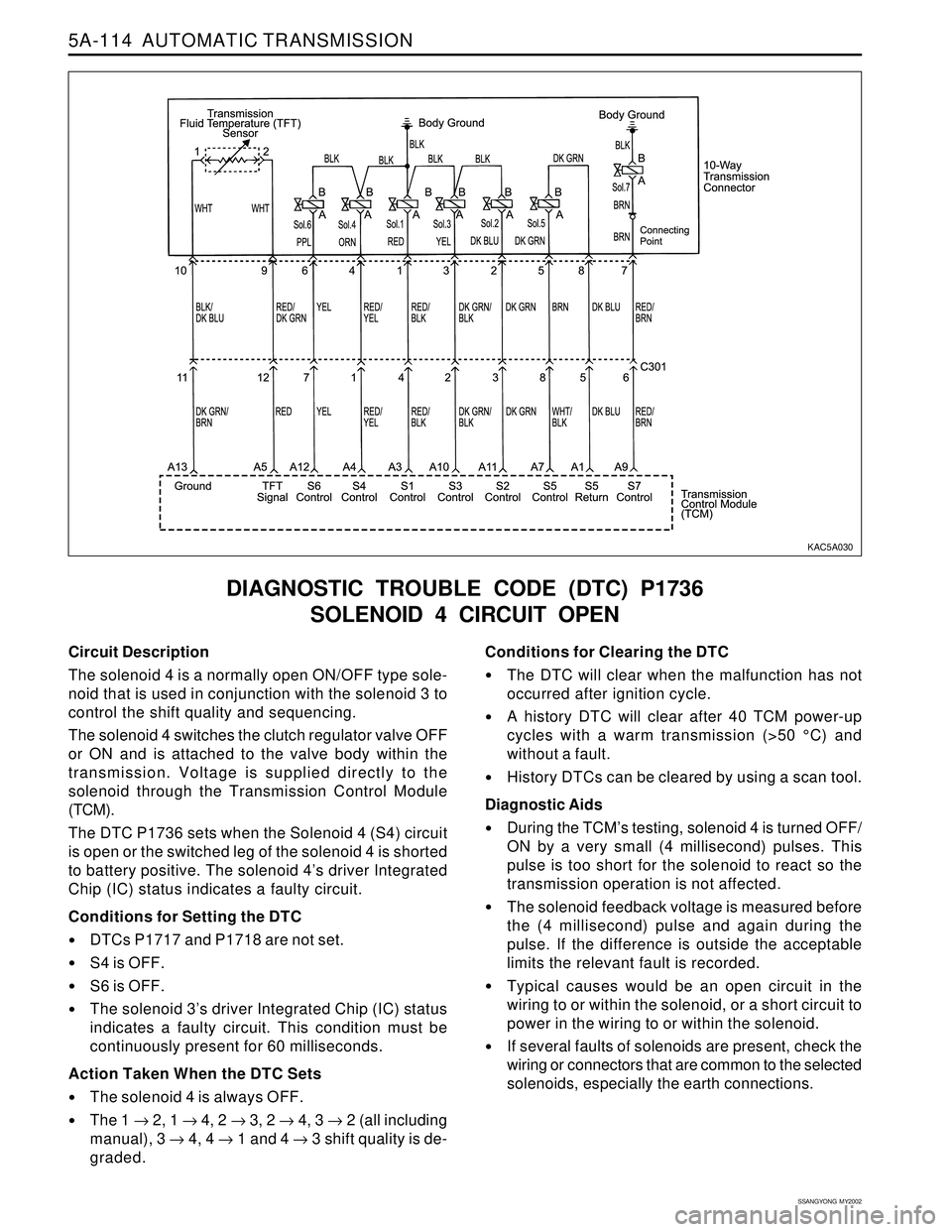
Circuit Description
The solenoid 4 is a normally open ON/OFF type sole-
noid that is used in conjunction with the solenoid 3 to
control the shift quality and sequencing.
The solenoid 4 switches the clutch regulator valve OFF
or ON and is attached to the valve body within the
transmission. Voltage is supplied directly to the
solenoid through the Transmission Control Module
(TCM).
The DTC P1736 sets when the Solenoid 4 (S4) circuit
is open or the switched leg of the solenoid 4 is shorted
to battery positive. The solenoid 4’s driver Integrated
Chip (IC) status indicates a faulty circuit.
Conditions for Setting the DTC
DTCs P1717 and P1718 are not set.
S4 is OFF.
S6 is OFF.
The solenoid 3’s driver Integrated Chip (IC) status
indicates a faulty circuit. This condition must be
continuously present for 60 milliseconds.
Action Taken When the DTC Sets
The solenoid 4 is always OFF.
The 1 → 2, 1 → 4, 2 → 3, 2 → 4, 3 → 2 (all including
manual), 3 → 4, 4 → 1 and 4 → 3 shift quality is de-
graded.
DIAGNOSTIC TROUBLE CODE (DTC) P1736
SOLENOID 4 CIRCUIT OPEN
Conditions for Clearing the DTC
The DTC will clear when the malfunction has not
occurred after ignition cycle.
A history DTC will clear after 40 TCM power-up
cycles with a warm transmission (>50 °C) and
without a fault.
History DTCs can be cleared by using a scan tool.
Diagnostic Aids
During the TCM’s testing, solenoid 4 is turned OFF/
ON by a very small (4 millisecond) pulses. This
pulse is too short for the solenoid to react so the
transmission operation is not affected.
The solenoid feedback voltage is measured before
the (4 millisecond) pulse and again during the
pulse. If the difference is outside the acceptable
limits the relevant fault is recorded.
Typical causes would be an open circuit in the
wiring to or within the solenoid, or a short circuit to
power in the wiring to or within the solenoid.
If several faults of solenoids are present, check the
wiring or connectors that are common to the selected
solenoids, especially the earth connections.
KAC5A030
Page 1237 of 2053
5A-142 AUTOMATIC TRANSMISSION
SSANGYONG MY2002
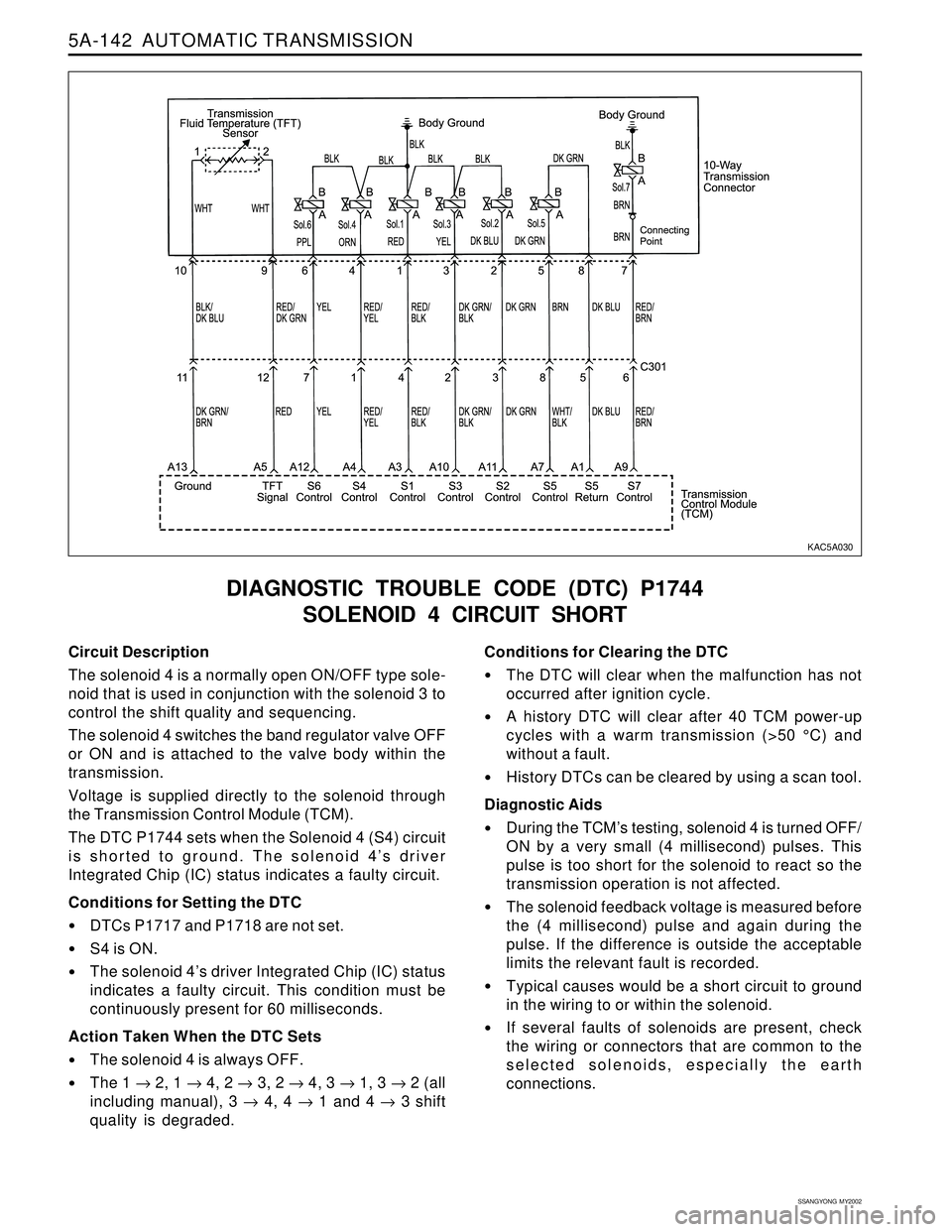
Circuit Description
The solenoid 4 is a normally open ON/OFF type sole-
noid that is used in conjunction with the solenoid 3 to
control the shift quality and sequencing.
The solenoid 4 switches the band regulator valve OFF
or ON and is attached to the valve body within the
transmission.
Voltage is supplied directly to the solenoid through
the Transmission Control Module (TCM).
The DTC P1744 sets when the Solenoid 4 (S4) circuit
is shorted to ground. The solenoid 4’s driver
Integrated Chip (IC) status indicates a faulty circuit.
Conditions for Setting the DTC
DTCs P1717 and P1718 are not set.
S4 is ON.
The solenoid 4’s driver Integrated Chip (IC) status
indicates a faulty circuit. This condition must be
continuously present for 60 milliseconds.
Action Taken When the DTC Sets
The solenoid 4 is always OFF.
The 1 → 2, 1 → 4, 2 → 3, 2 → 4, 3 → 1, 3 → 2 (all
including manual), 3 → 4, 4 → 1 and 4 → 3 shift
quality is degraded.
DIAGNOSTIC TROUBLE CODE (DTC) P1744
SOLENOID 4 CIRCUIT SHORT
Conditions for Clearing the DTC
The DTC will clear when the malfunction has not
occurred after ignition cycle.
A history DTC will clear after 40 TCM power-up
cycles with a warm transmission (>50 °C) and
without a fault.
History DTCs can be cleared by using a scan tool.
Diagnostic Aids
During the TCM’s testing, solenoid 4 is turned OFF/
ON by a very small (4 millisecond) pulses. This
pulse is too short for the solenoid to react so the
transmission operation is not affected.
The solenoid feedback voltage is measured before
the (4 millisecond) pulse and again during the
pulse. If the difference is outside the acceptable
limits the relevant fault is recorded.
Typical causes would be a short circuit to ground
in the wiring to or within the solenoid.
If several faults of solenoids are present, check
the wiring or connectors that are common to the
selected solenoids, especially the earth
connections.
KAC5A030
Page 1255 of 2053
5A-160 AUTOMATIC TRANSMISSION
SSANGYONG MY2002
UNIT REPAIR
REBUILD WARNINGS
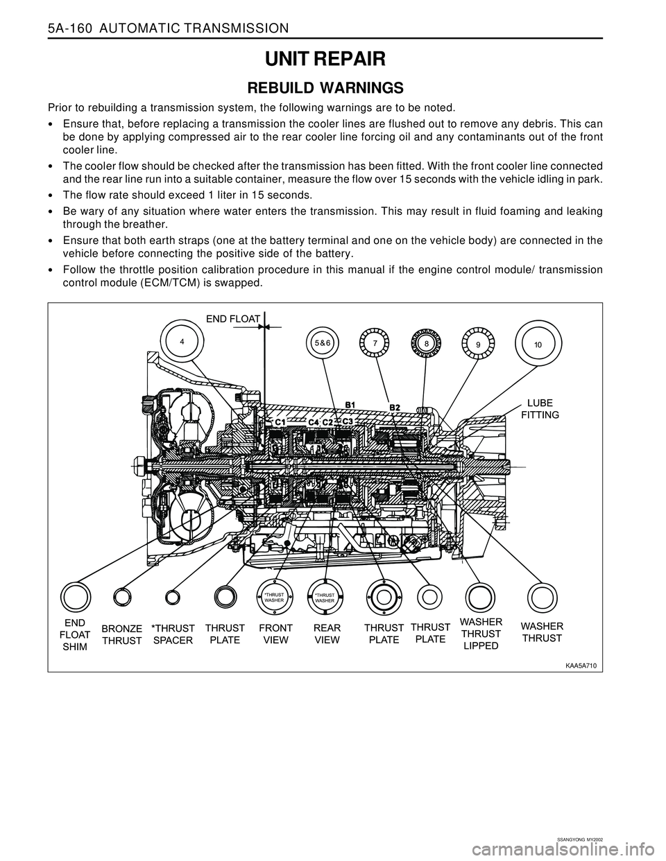
Prior to rebuilding a transmission system, the following warnings are to be noted.
Ensure that, before replacing a transmission the cooler lines are flushed out to remove any debris. This can
be done by applying compressed air to the rear cooler line forcing oil and any contaminants out of the front
cooler line.
The cooler flow should be checked after the transmission has been fitted. With the front cooler line connected
and the rear line run into a suitable container, measure the flow over 15 seconds with the vehicle idling in park.
The flow rate should exceed 1 liter in 15 seconds.
Be wary of any situation where water enters the transmission. This may result in fluid foaming and leaking
through the breather.
Ensure that both earth straps (one at the battery terminal and one on the vehicle body) are connected in the
vehicle before connecting the positive side of the battery.
Follow the throttle position calibration procedure in this manual if the engine control module/ transmission
control module (ECM/TCM) is swapped.
KAA5A710