1997 SSANGYONG KORANDO manual transmission
[x] Cancel search: manual transmissionPage 1126 of 2053
5A-32 AUTOMATIC TRANSMISSION
SSANGYONG MY2002
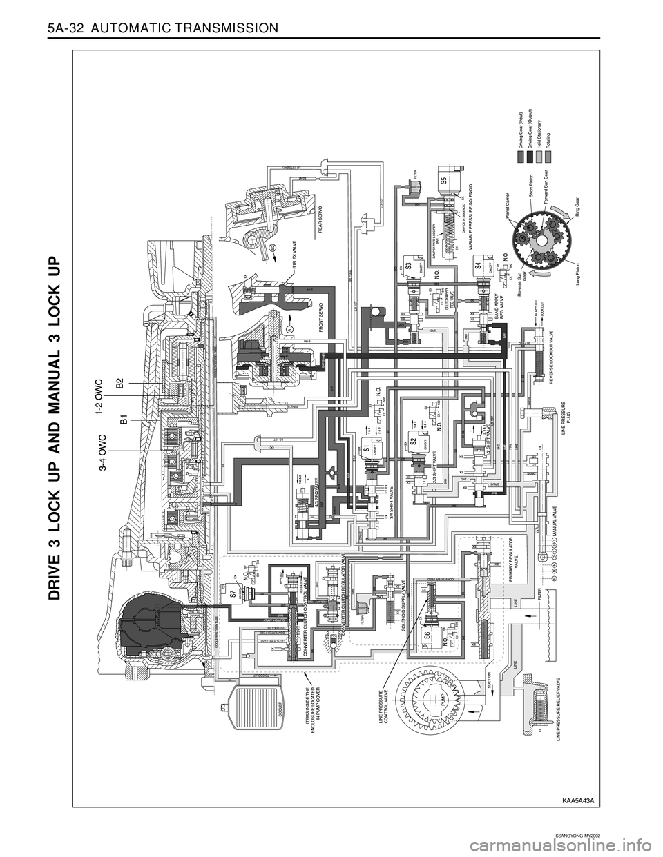
DRIVE 3 LOCK UP AND MANUAL 3 LOCK UP
KAA5A43A
Page 1127 of 2053
AUTOMATIC TRANSMISSION 5A-33
SSANGYONG MY2002
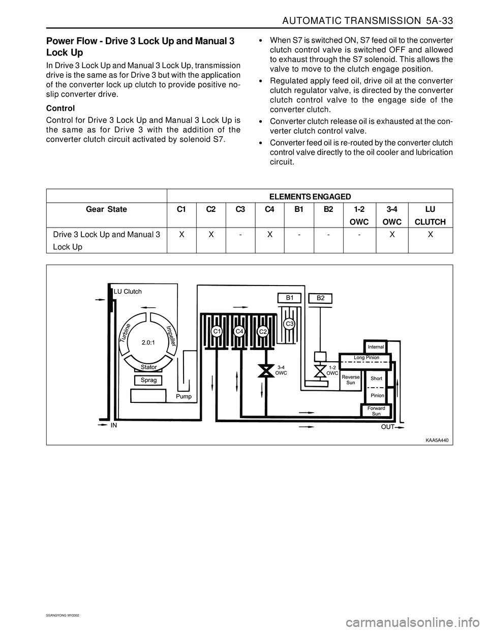
Power Flow - Drive 3 Lock Up and Manual 3
Lock Up
In Drive 3 Lock Up and Manual 3 Lock Up, transmission
drive is the same as for Drive 3 but with the application
of the converter lock up clutch to provide positive no-
slip converter drive.
Control
Control for Drive 3 Lock Up and Manual 3 Lock Up is
the same as for Drive 3 with the addition of the
converter clutch circuit activated by solenoid S7.
When S7 is switched ON, S7 feed oil to the converter
clutch control valve is switched OFF and allowed
to exhaust through the S7 solenoid. This allows the
valve to move to the clutch engage position.
Regulated apply feed oil, drive oil at the converter
clutch regulator valve, is directed by the converter
clutch control valve to the engage side of the
converter clutch.
Converter clutch release oil is exhausted at the con-
verter clutch control valve.
Converter feed oil is re-routed by the converter clutch
control valve directly to the oil cooler and lubrication
circuit.
Gear State
Drive 3 Lock Up and Manual 3
Lock UpC1
X
C2
XC3
-C4
XB1
-B2
-1-2
OWC
-3-4
OWC
XLU
CLUTCH
X ELEMENTS ENGAGED
KAA5A440
Page 1129 of 2053
AUTOMATIC TRANSMISSION 5A-35
SSANGYONG MY2002
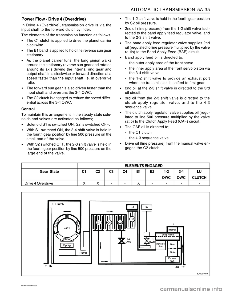
Power Flow - Drive 4 (Overdrive)
In Drive 4 (Overdrive), transmission drive is via the
input shaft to the forward clutch cylinder.
The elements of the transmission function as follows;
The C1 clutch is applied to drive the planet carrier
clockwise.
The B1 band is applied to hold the reverse sun gear
stationary.
As the planet carrier tuns, the long pinion walks
around the stationary reverse sun gear and rotates
around its axis driving the internal ring gear and
output shaft in a clockwise or forward direction at a
speed faster than the input shaft i.e. in overdrive
ratio.
The forward sun gear is also driven faster than the
input shaft and overruns the 3-4 OWC.
The C2 clutch is engaged to reduce the speed differ-
ential across the 3-4 OWC.
Control
To maintain this arrangement in the steady state sole-
noids and valves are activated as follows;
Solenoid S1 is switched ON. S2 is switched OFF.
With S1 switched ON, the 3-4 shift valve is held in
the fourth gear position by line 500 pressure on the
small end of the valve.
With S2 switched OFF, the 2-3 shift valve is held in
the fourth gear position by line 500 pressure on the
large end of the valve.
The 1-2 shift valve is held in the fourth gear position
by S2 oil pressure.
2nd oil (line pressure) from the 1-2 shift valve is di-
rected to the band apply feed regulator valve, and
to the 2-3 shift valve.
The band apply feed regulator valve supplies 2nd
oil (regulated to line pressure multiplied by the valve
ra-tio) to the Band Apply Feed (BAF) circuit.
Band apply feed oil is directed to;
- the outer apply area of the front servo
- the inner apply area of the front servo piston via
the 3-4 shift valve
- the 1-2 shift valve to provide an exhaust port
when the transmission is shifted to first gear
2nd oil at the 2-3 shift valve is directed to the 3rd
oil circuit.
3rd oil from the 2-3 shift valve is directed to the
clutch apply regulator valve, and to the 4-3
sequence valve.
The clutch apply regulator valve supplies oil (regu-
lated to line 500 pressure multiplied by the valve
ratio) to the Clutch Apply Feed (CAF) circuit.
The CAF oil is directed to;
- the C1 clutch
- the 4-3 sequence valve
Drive oil (line pressure) from the manual valve en-
gages the C2 clutch.
Gear State
Drive 4 Overdrive
C1
XC2
XC3
-C4
-B1
XB2
-1-2
OWC
-3-4
OWC
-LU
CLUTCH
- ELEMENTS ENGAGED
KAA5A460
Page 1132 of 2053
5A-38 AUTOMATIC TRANSMISSION
SSANGYONG MY2002
DIAGNOSIS
BASIC KNOWLEDGE REQUIRED
You must be familliar with some basic electronics to
use this section of the Service Manual. They will help
you to follow diagnostic procedures.
Notice: Lack of the basic knowledge of this transmis-
sion when performing diagnostic procedures could re-
sult in incorrect diagnostic performance or damage to
transmission components. Do not, under any circum-
stances, attempt to diagnose a transmission problem
without this basic knowledge.
Notice: If a wire is probed with a sharp instrument
and not properly sealed afterward, the wire will corrode
and an open circuit will result.
Diagnostic test probes are now available that allow
you to probe individual wires without leaving the wire
open to the environment. These probe devices are
inexpensive and easy to install, and they permanently
seal the wire from corrosion.
Special Tools
You should be able to use a Digital Volt Meter (DVM),
a circuit tester, jumper wires or leads and a line
pressure gauge set. The functional check procedure
is designed to verify the correct operation of electronic
components in the transmission. This will eliminate the
unnecessary removal of transmission components.
FUNCTIONAL CHECK
PROCEDURE
Begin with the Functional Check Procedure which pro-
vides a general outline of how to diagnose automatic
transmission. The following functional check procedure
will indicate the proper path of diagnosing the transmis-
sion by describing the basic checks and then referenc-
ing the locations of the specific checks.
Check the fluid level according to the Fluid Level
Service Procedure.
Check the transmission fluid leak.
Check if the transmission fluid is not burnt by smell.
Notice: The specific fluid used in this transmission
turns brown during normal operation. Brown fluid
does not indicate a transmission fault.
Ensure that the transmission is not in Limp Home
Mode (LHM).
Check the battery terminals and the earth connec-
tions for corrosion or looseness.
Check that the cooler flow is not restricted.
Check all electrical plug connections for tightness.
Use on-board diagnostic tool or a scan tool to see
if any transmission trouble codes have been set.
DIAGNOSTIC INFORMATION AND PROCEDURES
Refer to the appropriate “Diagnostic Trouble Code
(DTC)” information and repair the vehicle as
directed. After repairing the vehicle, perform the
road test and verify that the code has not set again.
Perform the Electrical/Garage Shift Tests.
Perform the Road Test Procedure in this section.
Inspect the oil and check for metal or other contami-
nants in the oil pan.
TRANSMISSION FLUID LEVEL
SERVICE PROCEDURE
This procedure is to be used when checking a concern
with the fluid level in a vehicle. A low fluid level will
result in slipping and loss of drive/ reverse or delay on
engagement of drive/ reverse when the vehicle is cold.
The vehicle is first checked for transmission diagnostic
messages on the scan tool. If the oil level is low, it is
possible to register a vehicle speed signal fault.
The vehicle is to be test driven to determine if there is
an abnormal delay when selecting drive or reverse, or
loss of drive. One symptom of low fluid level is a
momentary loss of drive when driving the vehicle around
a corner. Also when the transmission fluid level is low,
a loss of drive may occur when the transmission fluid
temperature is low.
If there is no loss of drive when the vehicle is driven
warm and a vehicle speed signal fault is registered,
then fluid should be added to the transmission.
When adding or changing transmission fluid use only
Castrol TQ 95 automatic transmission fluid. The use of
incorrect fluid will cause the performance and durability
of the transmission to be severely degraded.
Fluid Level Diagnosis procedure
1. If the vehicle is at operating temperature allow the
vehicle to cool down for two hours, but no greater
than four hours. Or if the vehicle is at cool status,
start the engine and allow the engine to idle for
approximately 5 minutes or, if possible, drive the
vehicle for a few kilometers. This will allow the
transmission to be within the correct temperature
range. Transmission fluid level should be checked
at temperature 50 - 60 °C (82 - 140 °F).
Caution: Removal of the fluid filler plug when
the transmission fluid is hot may cause injury if
fluid drains from the filler hole.
2. With the brake pedal pressed, move the gear shift
control lever through the gear ranges, pausing a
few seconds in each range. Return the gear shift
control lever to P (Park). Turn the engine OFF.
3. Park the vehicle on a hoist, inspection pit or similar
raised level surface. The vehicle must be control
level to obtain a correct fluid level measurement.
Page 1134 of 2053
5A-40 AUTOMATIC TRANSMISSION
SSANGYONG MY2002
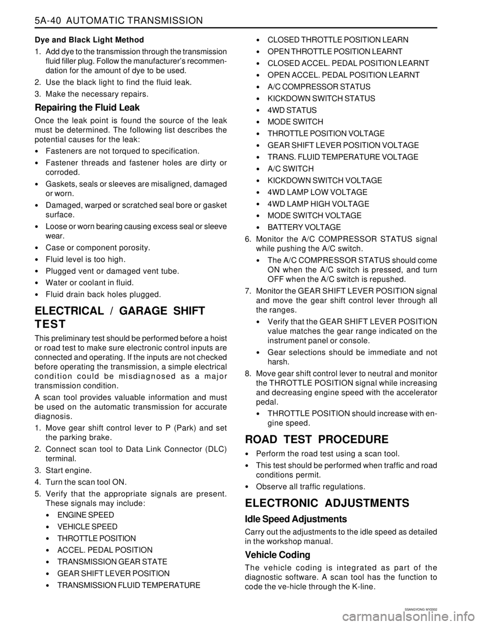
Dye and Black Light Method
1. Add dye to the transmission through the transmission
fluid filler plug. Follow the manufacturer’s recommen-
dation for the amount of dye to be used.
2. Use the black light to find the fluid leak.
3. Make the necessary repairs.
Repairing the Fluid Leak
Once the leak point is found the source of the leak
must be determined. The following list describes the
potential causes for the leak:
Fasteners are not torqued to specification.
Fastener threads and fastener holes are dirty or
corroded.
Gaskets, seals or sleeves are misaligned, damaged
or worn.
Damaged, warped or scratched seal bore or gasket
surface.
Loose or worn bearing causing excess seal or sleeve
wear.
Case or component porosity.
Fluid level is too high.
Plugged vent or damaged vent tube.
Water or coolant in fluid.
Fluid drain back holes plugged.
ELECTRICAL / GARAGE SHIFT
TEST
This preliminary test should be performed before a hoist
or road test to make sure electronic control inputs are
connected and operating. If the inputs are not checked
before operating the transmission, a simple electrical
condition could be misdiagnosed as a major
transmission condition.
A scan tool provides valuable information and must
be used on the automatic transmission for accurate
diagnosis.
1. Move gear shift control lever to P (Park) and set
the parking brake.
2. Connect scan tool to Data Link Connector (DLC)
terminal.
3. Start engine.
4. Turn the scan tool ON.
5. Verify that the appropriate signals are present.
These signals may include:
ENGINE SPEED
VEHICLE SPEED
THROTTLE POSITION
ACCEL. PEDAL POSITION
TRANSMISSION GEAR STATE
GEAR SHIFT LEVER POSITION
TRANSMISSION FLUID TEMPERATURE
CLOSED THROTTLE POSITION LEARN
OPEN THROTTLE POSITION LEARNT
CLOSED ACCEL. PEDAL POSITION LEARNT
OPEN ACCEL. PEDAL POSITION LEARNT
A/C COMPRESSOR STATUS
KICKDOWN SWITCH STATUS
4WD STATUS
MODE SWITCH
THROTTLE POSITION VOLTAGE
GEAR SHIFT LEVER POSITION VOLTAGE
TRANS. FLUID TEMPERATURE VOLTAGE
A/C SWITCH
KICKDOWN SWITCH VOLTAGE
4WD LAMP LOW VOLTAGE
4WD LAMP HIGH VOLTAGE
MODE SWITCH VOLTAGE
BATTERY VOLTAGE
6. Monitor the A/C COMPRESSOR STATUS signal
while pushing the A/C switch.
The A/C COMPRESSOR STATUS should come
ON when the A/C switch is pressed, and turn
OFF when the A/C switch is repushed.
7. Monitor the GEAR SHIFT LEVER POSITION signal
and move the gear shift control lever through all
the ranges.
Verify that the GEAR SHIFT LEVER POSITION
value matches the gear range indicated on the
instrument panel or console.
Gear selections should be immediate and not
harsh.
8. Move gear shift control lever to neutral and monitor
the THROTTLE POSITION signal while increasing
and decreasing engine speed with the accelerator
pedal.
THROTTLE POSITION should increase with en-
gine speed.
ROAD TEST PROCEDURE
Perform the road test using a scan tool.
This test should be performed when traffic and road
conditions permit.
Observe all traffic regulations.
ELECTRONIC ADJUSTMENTS
Idle Speed Adjustments
Carry out the adjustments to the idle speed as detailed
in the workshop manual.
Vehicle Coding
The vehicle coding is integrated as part of the
diagnostic software. A scan tool has the function to
code the ve-hicle through the K-line.
Page 1135 of 2053
5A-40 AUTOMATIC TRANSMISSION
SSANGYONG MY2002
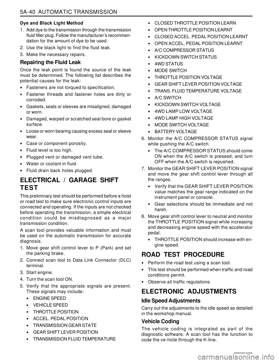
Dye and Black Light Method
1. Add dye to the transmission through the transmission
fluid filler plug. Follow the manufacturer’s recommen-
dation for the amount of dye to be used.
2. Use the black light to find the fluid leak.
3. Make the necessary repairs.
Repairing the Fluid Leak
Once the leak point is found the source of the leak
must be determined. The following list describes the
potential causes for the leak:
Fasteners are not torqued to specification.
Fastener threads and fastener holes are dirty or
corroded.
Gaskets, seals or sleeves are misaligned, damaged
or worn.
Damaged, warped or scratched seal bore or gasket
surface.
Loose or worn bearing causing excess seal or sleeve
wear.
Case or component porosity.
Fluid level is too high.
Plugged vent or damaged vent tube.
Water or coolant in fluid.
Fluid drain back holes plugged.
ELECTRICAL / GARAGE SHIFT
TEST
This preliminary test should be performed before a hoist
or road test to make sure electronic control inputs are
connected and operating. If the inputs are not checked
before operating the transmission, a simple electrical
condition could be misdiagnosed as a major
transmission condition.
A scan tool provides valuable information and must
be used on the automatic transmission for accurate
diagnosis.
1. Move gear shift control lever to P (Park) and set
the parking brake.
2. Connect scan tool to Data Link Connector (DLC)
terminal.
3. Start engine.
4. Turn the scan tool ON.
5. Verify that the appropriate signals are present.
These signals may include:
ENGINE SPEED
VEHICLE SPEED
THROTTLE POSITION
ACCEL. PEDAL POSITION
TRANSMISSION GEAR STATE
GEAR SHIFT LEVER POSITION
TRANSMISSION FLUID TEMPERATURE
CLOSED THROTTLE POSITION LEARN
OPEN THROTTLE POSITION LEARNT
CLOSED ACCEL. PEDAL POSITION LEARNT
OPEN ACCEL. PEDAL POSITION LEARNT
A/C COMPRESSOR STATUS
KICKDOWN SWITCH STATUS
4WD STATUS
MODE SWITCH
THROTTLE POSITION VOLTAGE
GEAR SHIFT LEVER POSITION VOLTAGE
TRANS. FLUID TEMPERATURE VOLTAGE
A/C SWITCH
KICKDOWN SWITCH VOLTAGE
4WD LAMP LOW VOLTAGE
4WD LAMP HIGH VOLTAGE
MODE SWITCH VOLTAGE
BATTERY VOLTAGE
6. Monitor the A/C COMPRESSOR STATUS signal
while pushing the A/C switch.
The A/C COMPRESSOR STATUS should come
ON when the A/C switch is pressed, and turn
OFF when the A/C switch is repushed.
7. Monitor the GEAR SHIFT LEVER POSITION signal
and move the gear shift control lever through all
the ranges.
Verify that the GEAR SHIFT LEVER POSITION
value matches the gear range indicated on the
instrument panel or console.
Gear selections should be immediate and not
harsh.
8. Move gear shift control lever to neutral and monitor
the THROTTLE POSITION signal while increasing
and decreasing engine speed with the accelerator
pedal.
THROTTLE POSITION should increase with en-
gine speed.
ROAD TEST PROCEDURE
Perform the road test using a scan tool.
This test should be performed when traffic and road
conditions permit.
Observe all traffic regulations.
ELECTRONIC ADJUSTMENTS
Idle Speed Adjustments
Carry out the adjustments to the idle speed as detailed
in the workshop manual.
Vehicle Coding
The vehicle coding is integrated as part of the
diagnostic software. A scan tool has the function to
code the ve-hicle through the K-line.
Page 1136 of 2053
AUTOMATIC TRANSMISSION 5A-41
SSANGYONG MY2002
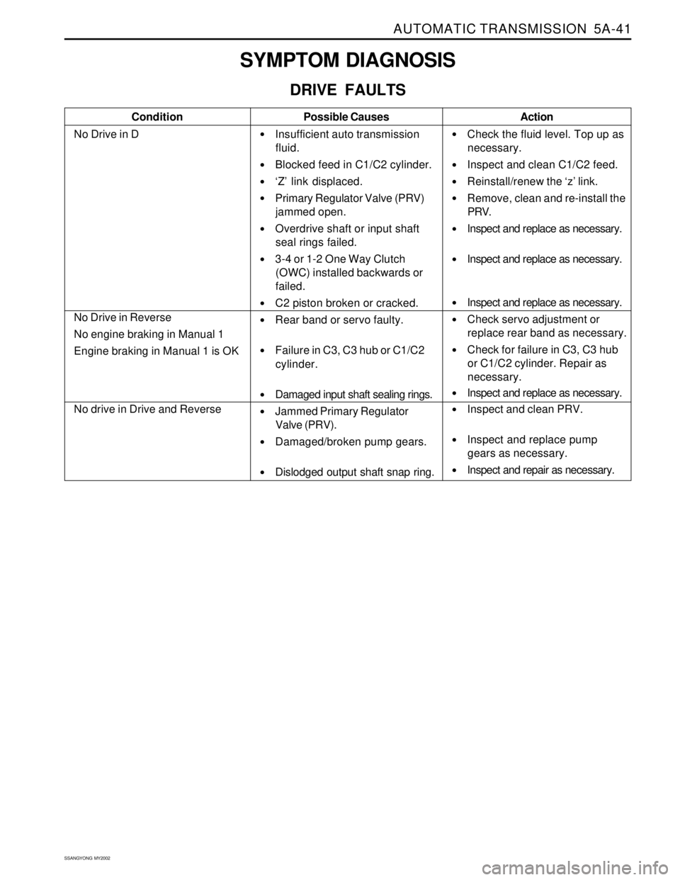
SYMPTOM DIAGNOSIS
DRIVE FAULTS
Condition
No Drive in DPossible Causes
Insufficient auto transmission
fluid.
Blocked feed in C1/C2 cylinder.
‘Z’ link displaced.
Primary Regulator Valve (PRV)
jammed open.
Overdrive shaft or input shaft
seal rings failed.
3-4 or 1-2 One Way Clutch
(OWC) installed backwards or
failed.
C2 piston broken or cracked.
Rear band or servo faulty.
Failure in C3, C3 hub or C1/C2
cylinder.
Damaged input shaft sealing rings.
Jammed Primary Regulator
Valve (PRV).
Damaged/broken pump gears.
Dislodged output shaft snap ring.Action
Check the fluid level. Top up as
necessary.
Inspect and clean C1/C2 feed.
Reinstall/renew the ‘z’ link.
Remove, clean and re-install the
PRV.
Inspect and replace as necessary.
Inspect and replace as necessary.
Inspect and replace as necessary.
Check servo adjustment or
replace rear band as necessary.
Check for failure in C3, C3 hub
or C1/C2 cylinder. Repair as
necessary.
Inspect and replace as necessary.
Inspect and clean PRV.
Inspect and replace pump
gears as necessary.
Inspect and repair as necessary.
No Drive in Reverse
No engine braking in Manual 1
Engine braking in Manual 1 is OK
No drive in Drive and Reverse
Page 1137 of 2053
5A-42 AUTOMATIC TRANSMISSION
SSANGYONG MY2002
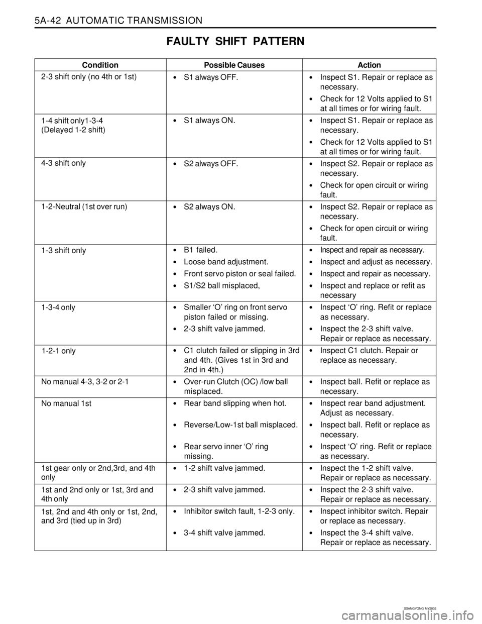
FAULTY SHIFT PATTERN
Condition
2-3 shift only (no 4th or 1st)Possible Causes
S1 always OFF.
S1 always ON.
S2 always OFF.
S2 always ON.
B1 failed.
Loose band adjustment.
Front servo piston or seal failed.
S1/S2 ball misplaced,
Smaller ‘O’ ring on front servo
piston failed or missing.
2-3 shift valve jammed.
C1 clutch failed or slipping in 3rd
and 4th. (Gives 1st in 3rd and
2nd in 4th.)
Over-run Clutch (OC) /low ball
misplaced.
Rear band slipping when hot.
Reverse/Low-1st ball misplaced.
Rear servo inner ‘O’ ring
missing.
1-2 shift valve jammed.
2-3 shift valve jammed.
Inhibitor switch fault, 1-2-3 only.
3-4 shift valve jammed.Action
Inspect S1. Repair or replace as
necessary.
Check for 12 Volts applied to S1
at all times or for wiring fault.
Inspect S1. Repair or replace as
necessary.
Check for 12 Volts applied to S1
at all times or for wiring fault.
Inspect S2. Repair or replace as
necessary.
Check for open circuit or wiring
fault.
Inspect S2. Repair or replace as
necessary.
Check for open circuit or wiring
fault.
Inspect and repair as necessary.
Inspect and adjust as necessary.
Inspect and repair as necessary.
Inspect and replace or refit as
necessary
Inspect ‘O’ ring. Refit or replace
as necessary.
Inspect the 2-3 shift valve.
Repair or replace as necessary.
Inspect C1 clutch. Repair or
replace as necessary.
Inspect ball. Refit or replace as
necessary.
Inspect rear band adjustment.
Adjust as necessary.
Inspect ball. Refit or replace as
necessary.
Inspect ‘O’ ring. Refit or replace
as necessary.
Inspect the 1-2 shift valve.
Repair or replace as necessary.
Inspect the 2-3 shift valve.
Repair or replace as necessary.
Inspect inhibitor switch. Repair
or replace as necessary.
Inspect the 3-4 shift valve.
Repair or replace as necessary.
1-4 shift only1-3-4
(Delayed 1-2 shift)
4-3 shift only
1-2-Neutral (1st over run)
1-3 shift only
1-3-4 only
1-2-1 only
No manual 4-3, 3-2 or 2-1
No manual 1st
1st gear only or 2nd,3rd, and 4th
only
1st and 2nd only or 1st, 3rd and
4th only
1st, 2nd and 4th only or 1st, 2nd,
and 3rd (tied up in 3rd)