Page 1259 of 2053
5A-164 AUTOMATIC TRANSMISSION
SSANGYONG MY2002
5. Using cross shaft pin remover/installer (detent le-
ver) 0555-336258, press the pin from the cross
shaft and withdraw the shaft from the case.
6. Remove the cross shaft pin and spring.
7. Remove the manual valve lever and the park rod.
8. Depress the tangs and withdraw the 10 pin
connector into the case. Remove the wiring loom
assembly.
9. Detach the No. 7 solenoid wire from the front of
the case.
10. Remove the parking pawl pivot pin and the pawl
and spring from the case.
11. Remove the shaft and the rear servo lever.
12. Remove the rear servo cover and piston assembly.
13. Remove the B1R circlip, valve and spring.
14. Remove both band adjustment shims.
15. Inspect the output shaft bushing in the case and
replace if necessary.
16. Inspect cooler line fittings and replace as
necessary.
17. Inspect the case for damage.
KAA5A600
KAA5A610
KAA5A620
KAA5A630
Page 1264 of 2053
AUTOMATIC TRANSMISSION 5A-169
SSANGYONG MY2002
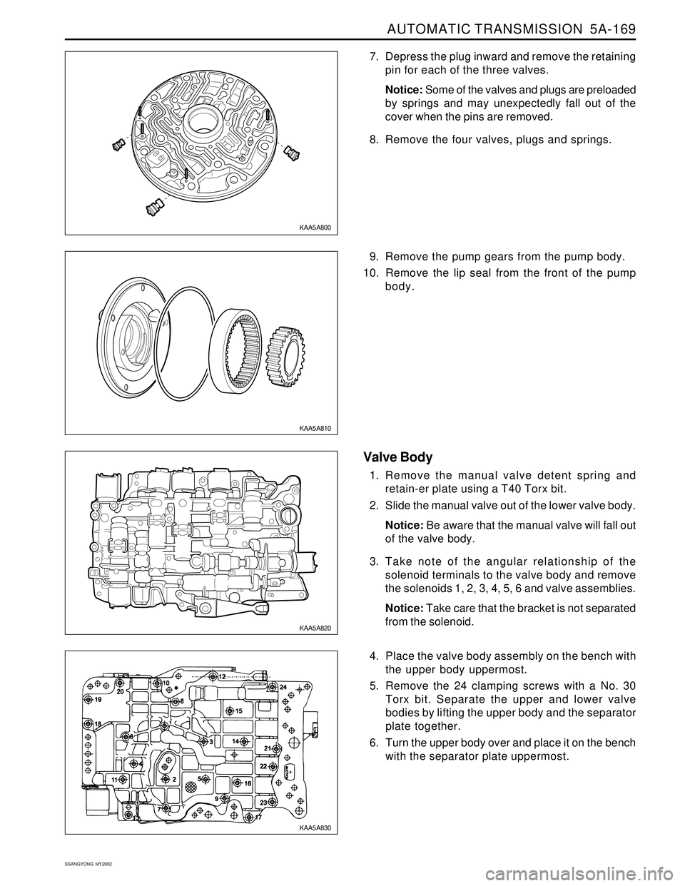
7. Depress the plug inward and remove the retaining
pin for each of the three valves.
Notice: Some of the valves and plugs are preloaded
by springs and may unexpectedly fall out of the
cover when the pins are removed.
8. Remove the four valves, plugs and springs.
9. Remove the pump gears from the pump body.
10. Remove the lip seal from the front of the pump
body.
Valve Body
1. Remove the manual valve detent spring and
retain-er plate using a T40 Torx bit.
2. Slide the manual valve out of the lower valve body.
Notice: Be aware that the manual valve will fall out
of the valve body.
3. Take note of the angular relationship of the
solenoid terminals to the valve body and remove
the solenoids 1, 2, 3, 4, 5, 6 and valve assemblies.
Notice: Take care that the bracket is not separated
from the solenoid.
4. Place the valve body assembly on the bench with
the upper body uppermost.
5. Remove the 24 clamping screws with a No. 30
Torx bit. Separate the upper and lower valve
bodies by lifting the upper body and the separator
plate together.
6. Turn the upper body over and place it on the bench
with the separator plate uppermost.
KAA5A800
KAA5A810
KAA5A820
KAA5A830
Page 1267 of 2053
5A-172 AUTOMATIC TRANSMISSION
SSANGYONG MY2002
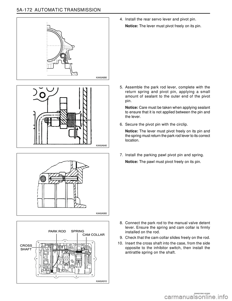
4. Install the rear servo lever and pivot pin.
Notice: The lever must pivot freely on its pin.
5. Assemble the park rod lever, complete with the
return spring and pivot pin, applying a small
amount of sealant to the outer end of the pivot
pin.
Notice: Care must be taken when applying sealant
to ensure that it is not applied between the pin and
the lever.
6. Secure the pivot pin with the circlip.
Notice: The lever must pivot freely on its pin and
the spring must return the park rod lever to its correct
location.
7. Install the parking pawl pivot pin and spring.
Notice: The pawl must pivot freely on its pin.
8. Connect the park rod to the manual valve detent
lever. Ensure the spring and cam collar is firmly
installed on the rod.
9. Check that the cam collar slides freely on the rod.
10. Insert the cross shaft into the case, from the side
opposite to the inhibitor switch, then install the
antirattle spring on the shaft.
KAA5A890
KAA5A640
KAA5A900
KAA5A910
Page 1268 of 2053
AUTOMATIC TRANSMISSION 5A-173
SSANGYONG MY2002
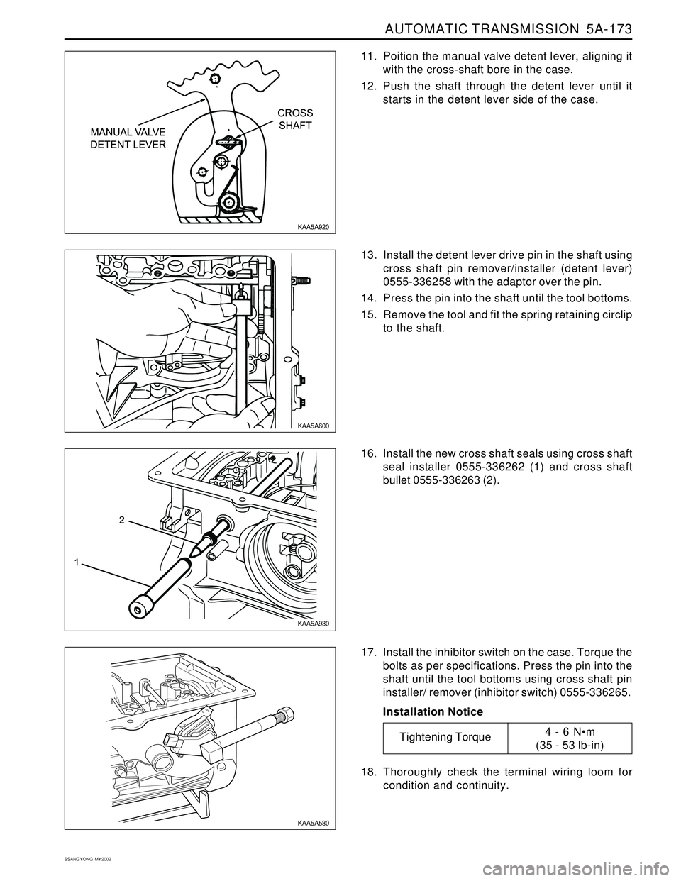
11. Poition the manual valve detent lever, aligning it
with the cross-shaft bore in the case.
12. Push the shaft through the detent lever until it
starts in the detent lever side of the case.
16. Install the new cross shaft seals using cross shaft
seal installer 0555-336262 (1) and cross shaft
bullet 0555-336263 (2).
17. Install the inhibitor switch on the case. Torque the
bolts as per specifications. Press the pin into the
shaft until the tool bottoms using cross shaft pin
installer/ remover (inhibitor switch) 0555-336265.
Installation Notice
18. Thoroughly check the terminal wiring loom for
condition and continuity. 13. Install the detent lever drive pin in the shaft using
cross shaft pin remover/installer (detent lever)
0555-336258 with the adaptor over the pin.
14. Press the pin into the shaft until the tool bottoms.
15. Remove the tool and fit the spring retaining circlip
to the shaft.
KAA5A920
KAA5A600
KAA5A930
KAA5A580
Tightening Torque4 - 6 Nm
(35 - 53 lb-in)
Page 1291 of 2053
5A-196 AUTOMATIC TRANSMISSION
SSANGYONG MY2002
21. Install solenoid 5. Ensure that the solenoid is
pushed firmly into the valve body by the retainer
and that the screw is tightened to specification.
Installation Notice
22. Install the detent spring assembly (spring, support
plate and screw), ensuring that the screw is tight-
ened to specification. Check the spring for wear
or damage.
Installation Notice
23. Install the manual shift valve.
Notice: Be aware that the manual valve will fall out
of the valve body.
24. Align the valve body assembly on the
transmission case and install the manual valve
lever to manual valve link. Fit the long end of the
link to the manual valve first. Install the securing
bolts and tighten to specification in the specified
sequence.
Installation Notice
KAA5A1Y0 KAA5A1X0
KAA5A1Z0 KAA5A1W0
Tightening Torque8 - 12 Nm
(71 - 106 lb-in)
Tightening Torque20 - 22 Nm
(15 - 16 lb-ft)
Tightening Torque8 - 13 Nm
(71 - 115 lb-in)
Page 1292 of 2053
AUTOMATIC TRANSMISSION 5A-197
SSANGYONG MY2002
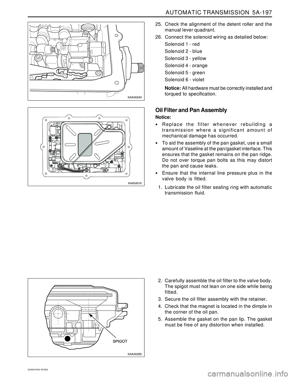
2. Carefully assemble the oil filter to the valve body.
The spigot must not lean on one side while being
fitted.
3. Secure the oil filter assembly with the retainer.
4. Check that the magnet is located in the dimple in
the corner of the oil pan.
5. Assemble the gasket on the pan lip. The gasket
must be free of any distortion when installed. 25. Check the alignment of the detent roller and the
manual lever quadrant.
26. Connect the solenoid wiring as detailed below:
Solenoid 1 - red
Solenoid 2 - bIue
Solenoid 3 - yellow
Solenoid 4 - orange
Solenoid 5 - green
Solenoid 6 - violet
Notice: All hardware must be correctly installed and
torqued to specification.
Oil Filter and Pan Assembly
Notice:
Replace the filter whenever rebuilding a
transmission where a significant amount of
mechanical damage has occurred.
To aid the assembly of the pan gasket, use a small
amount of Vaseline at the pan/gasket interface. This
ensures that the gasket remains on the pan ridge.
Do not over torque pan bolts as this may distort
the pan and cause leaks.
Ensure that the internal line pressure plus in the
valve body is fitted.
1. Lubricate the oil filter sealing ring with automatic
transmission fluid.
KAA5A2B0 KAA5A2A0
KAA5A510
Page 1299 of 2053
5A-204 AUTOMATIC TRANSMISSION
SSANGYONG MY2002
Speed limitations inhibiting Downshift Downshift Type Max.
1/2
12
32
57
573L
-
-
-
119 2/3
24
66
110
1104L
82
117
170
175 1/2
12
24
57
573/4
39
93
170
175 3L
-
70
114
119 2/3
20
50
110
1104L
82
93
170
175 NORMA MODE
E32 Typical Shift Patterns
THROTTLE
OPENING
0 %
45 %
100 % (WOT)
Kickdown
POWER MODE
SHIFT (km/h)THROTTLE
OPENING
0 %
45 %
100 % (WOT)
KickdownSHIFT (km/h)
Typical Manual Downshift Maximum Speed
Manual 2-1
Manual 3-2
Manual 4-3
Manual 4-2 (4-2 direct)
Manual 4-2 (4-3-2 sequence)61 kph (37.9 mph)
117 kph (72.7 mph)
149 kph (92.5 mph)
64 kph (39.8 mph)
117 kph (72.7 mph)
1/2
12
31
47
483/4
42
97
147
150 3L
-
-
-
96 2/3
23
64
92
944L
75
94
147
150 1/2
10
23
47
483/4
36
72
147
150 3L
-
75
95
96 2/3
19
46
92
944L
79
92
147
150 NORMA MODE
E23 Typical Shift Patterns
THROTTLE
OPENING
0 %
50 %
100 % (WOT)
Kickdown
POWER MODE
SHIFT (km/h)THROTTLE
OPENING
0 %
50 %
100 % (WOT)
KickdownSHIFT (km/h)3/4
41
105
170
175
Page 1309 of 2053
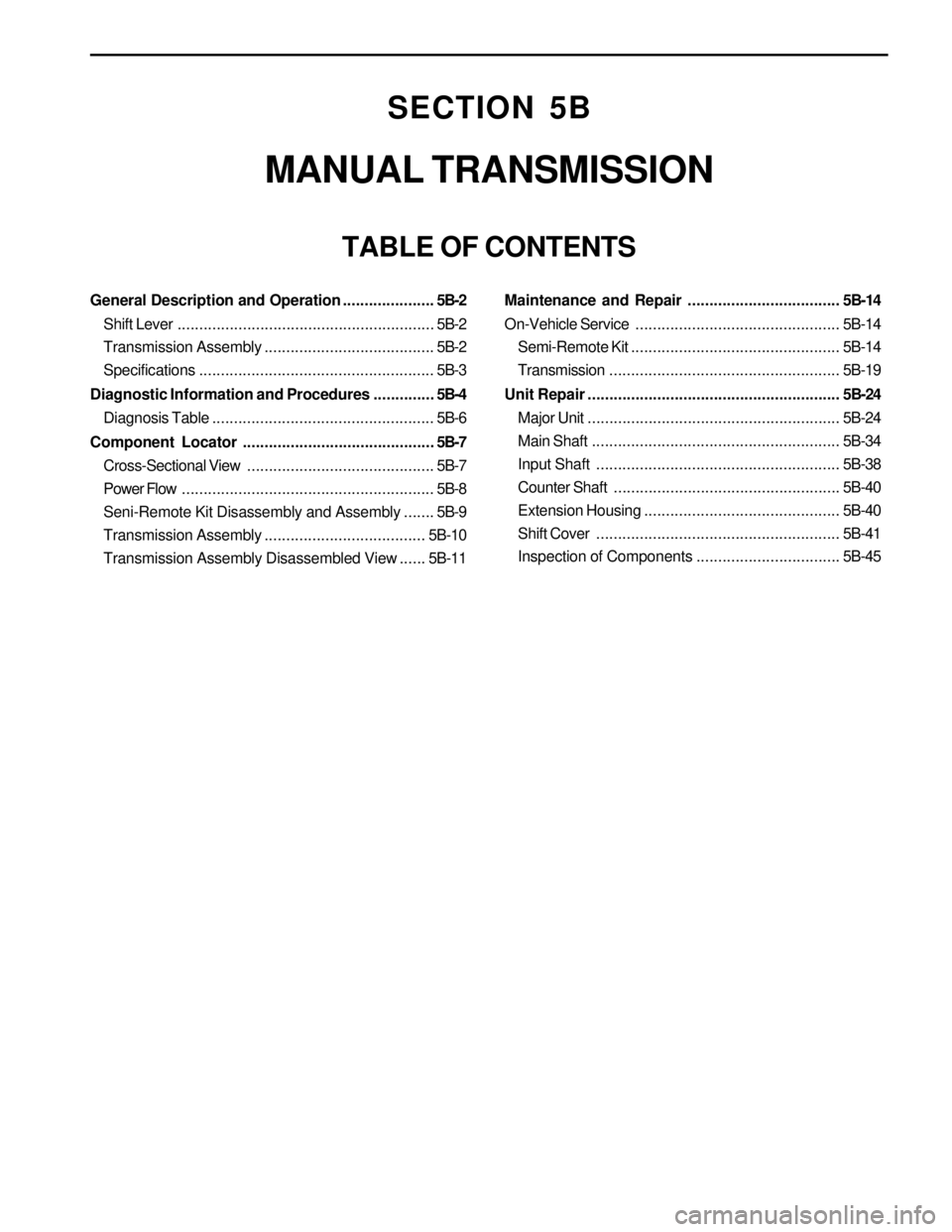
SECTION 5B
MANUAL TRANSMISSION
TABLE OF CONTENTS
General Description and Operation.....................5B-2
Shift Lever...........................................................5B-2
Transmission Assembly.......................................5B-2
Specifications......................................................5B-3
Diagnostic Information and Procedures..............5B-4
Diagnosis Table...................................................5B-6
Component Locator............................................5B-7
Cross-Sectional View ...........................................5B-7
Power Flow..........................................................5B-8
Seni-Remote Kit Disassembly and Assembly.......5B-9
Transmission Assembly.....................................5B-10
Transmission Assembly Disassembled View......5B-11Maintenance and Repair................................... 5B-14
On-Vehicle Service...............................................5B-14
Semi-Remote Kit................................................5B-14
Transmission.....................................................5B-19
Unit Repair.......................................................... 5B-24
Major Unit..........................................................5B-24
Main Shaft.........................................................5B-34
Input Shaft........................................................5B-38
Counter Shaft....................................................5B-40
Extension Housing.............................................5B-40
Shift Cover........................................................5B-41
Inspection of Components.................................5B-45