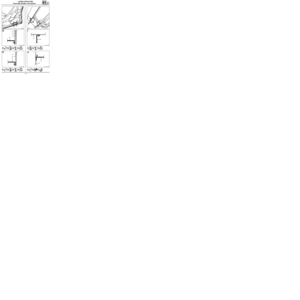
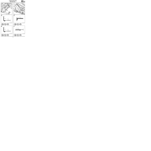
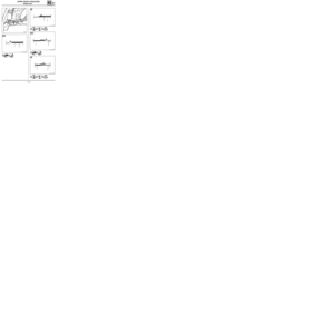
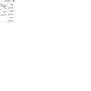
Page 9 of 255
GENERAL
Identification
40
Numbers given on the manufacturer’s plate and on the engine plate should be quoted in all letters or
orders.
1 The type mines of the vehicle and the chassis number
2 The total all up weight(P.T.M.A.)
3 The maximum permitted total train weight (P.T.R. - vehicle loaded with trailer)
4 The maximum permitted weight on the front axle (P.T.M.A. front axle)
5 The maximum permitted weight on the rear axle (P.T.M.A. rear axle)
6 The technical features of the vehicle
7 The paint reference
8 The equipment level
9 The vehicle type
10 The trim code
11 The additional equipment definition
12 The fabrication number
13 The interior matching trim code
e0-00/00-0000-000-000-00
VF000000000000000
0000 kg
0000 kg
1
- 0000 kg
2
- 0000 kg
000000000000000RENAULT S.A.
1
2
3
4
5
8 7
6
9
10
13
12 11
40-5
Page 10 of 255

GENERAL
Means of lifting
40
AXLE STANDS
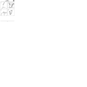
To place the vehicle on axle stands, they MUSTbe
placed:
- either under the reinforcements provided for
lifting the vehicle with the jack which forms
part of the vehicle equipment,
- or under the points behind the reinforcements.
Rear positioning of the axle stands can be carried
out by lifting the vehicle from the side.
Safety symbol (special precautions to be taken when carrying out operations).
SPECIAL TOOLING REQUIRED
Cha. 280 -02 Adaptable cross piece for trolley
jack
Cha. 408 -01
or Adaptable socket for trolley jack
Cha. 408 -02
If a trolley jack is used, appropriate axle
stands must always be used.
The vehicle MUST NOT be lifted by supporting its
weight under the front suspension arms, or under
the V section rear axle.
According to the type of trolley jack, use sockets
Cha. 408-01 or Cha. 408-02 to position the cross
piece Cha. 280-02.
To lift at the front or rear, take the weight under
the vehicle jacking points.
LIFTING FROM THE SIDE WITH A TROLLEY JACK
Use cross piece Cha. 280-02.
Take the weight under the valance at the front
door.
Position the flange correctly in the cross member
groove.
12333-2G
12274-1R
85679-1G15
40-6
Page 11 of 255
GENERAL
Means of lifting
40
SAFETY SYMBOL
There are several examples :
1 - WHEN REMOVING PARTS
Generally speaking, never use a 2 post lift if a
four post lift would be more suitable.
If this is not possible, position the lifting pads
below the body flange at the jacking points for
the jack supplied with the vehicle.
98703S
FRONT
98704S
REAR
These absolutely MUST be placed to the right of
the jacking points. They must be clipped into the
sill panel flange openings.
2 -
SPECIAL CASE OF THE REMOVAL - REFITTING
OF THE ENGINE AND TRANSMISSION
ASSEMBLY
In this specific case, the body of the vehicle must
be attached to the arms of the two post lift with
special pads.
FOG Company
Part number FOG 449 8111 - 449 8411
or
CHEMICO Company
Part number 39 2550 0001
or
SCHENCH Company
Part number 776 684
40-7
Page 12 of 255
GENERAL
Towing
40
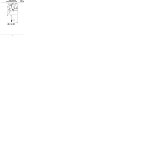
FRONT OBSERVE THE LEGAL TOWING REQUIREMENTS OF THE COUNTRY YOU ARE IN.
NEVER USE THE DRIVESHAFTS AS ATTACHMENT POINTS.
The towing points may only be used for towing the vehicle on the road. They should never be used for remo-
ving the vehicle from a ditch or for any other similar breakdown operation or to lift the vehicle, either direct-
ly or indirectly.
REAR
13366S13189S
40-8
Page 13 of 255

GENERAL
Using symbols
40
11644R1
The above diagram shows parts on the vehicle for
which a section of the panel butt welding joint is
shown by the diagrams which follow.
This dashed line shows the centre line
of the sections
The point shows the exact position of
the weld join
This letter designates the drawing
corresponding to the section (It is gi-
ven in one of the upper corners of
each drawing )
F - G -
H - I - J
CAA11538R8
G
1
e = 1+1 7The following indications are found in the section
diagrams :
The part in black is the one which will
be removed in the operation
are the part numbers corresponding to
the list on the introduction page 1
and 7
e = 1 + 1are the thicknesses (in mm) of the
panels for electrical spot welding
This arrow on the diagram designates
the access point for the unpicking of
spot welds (see specific cases)
It also indicates the logical sequence of operations
in the symbols which follow each diagram.
place of operation and logical sequence
spot welding
weldable mastic
unpicking with grinder
Example :
40-9
Page 14 of 255
GENERAL
Using symbols
40
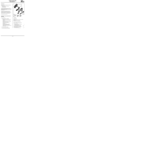
The references which follow indicate different
operations :
unpicking
welding
SPECIFIC CASES
CAA11537-1R6
J
1 2
In this example, there is no direct access for remo-
ving part 1. The spot welds should be unpicked
through part 2, which should be kept.
CAQ11697-1R5
I
1 2
1
2
This arrow indicates that it is necessary
to cut the part it crosses before acces-
sing the joint
.
Under diagram I
1
2
unpicking
with grinderapply weld fillet1st opera-
tion
site of operation and order of operations
10354R
D
In this particular case, the arrow indicates that
the joint is made by arc welding (MIG).
10349R
E
In this example, the joint is
made by bonding.
chisel the edge2nd opera-
tion
1 2
1
2
40-10
Page 15 of 255

GENERAL
Key to Symbols
40
- Cutting out part by grinding off flange
or grinding back remaining traces of
spot weld.
- Finish surface after welding.
- Angle grinder equipped with a rubber
pad and a 120 to 180 mm diameter
fibre disc grain size P36. Chiselling
Grind back beads or spot welds.
Straight grinding wheel with 75 mm
diameter bakelite impregnated disc,
thickness 1.8 to 3.2 mm.
Grind back spot welds.
20 000 rpm straight grinder with 10 or 16
mm diameter spherical burr.
Drill spot welds.
Hardened steel bit. Speed of rotation 800
to 1 000 rpm.
Unpicking
Cleaning surfaces to be welded.
100 mm diameter fibre disc.
Cutting with a saw.
Pneumatic power hacksaw.
Unsoldering.
Plug welding.
Under MAG gas protection.
Crimping of exterior door panels.
Safety symbol.
This means that the welding operation
in question concerns one or more of the
vehicle’s vital safety components.
Body solder - lead fill.
Hot air torch.
Nozzle output temperature 600° min.
Slipper+ 33 % tin solder + tallow.
Note : to a large extent, body solder
filling compensates for the heat
distortion caused by welding.
Application of weldable mastic.
This mastic conducts electricity, applied
between two panels to be spot welded,
it ensures the seal between the panels
and avoids corrosion of the spot welds.
Application of aluminium paint.
This is to be applied to the joint faces of
each of the parts to be plug welded.
The paint conducts electricity and is is
resistant to high temperatures. It
provides anti-corrosion protection
around the plug welds.
Apply a fillet of extruded mastic
• from a manual or pneumatic spray
gun.
• one or two pot mastic for crimped
and butt joints.
Spray on sealer
• spray gun.
• two pot anti-gravel and anti-
corrosion mastic.
MAG stitch weld
Note : to obtain a good quality weld we
recommend the use of a gas consisting
of argon + 15 % CO2. This is
considered to be an active gas (MAG).
Spot weld
40-11
Page 16 of 255
GENERAL
Description of parts (exploded view)
40
PRB4002
1 Rear floor, front section
2 Rear floor unit
3 Rear floor, rear section
4 Rear end cross member
5 Rear end panel
6 Rear absorber reinforcement
7 Complete rear side member
8 Rear side member extension
9 Rear side member, part section
10 Rear floor stiffener
11 Rear floor centre cross member
12 Seat anchoring reinforcement13 Rear floor front cross member
14 Front side member, rear section
15 Front side cross member
16 Front side member, front section
17 Front mounting of front sub-frame
18 Front side member closure panel
19 Front end lower cross member
20 Front half unit
21 Tunnel
22 Side floor
23 Sill panel closure panel (side door)
24 Cross member under front seat
SUB-FRAME
40-12