Page 1945 of 2890
OBD0229
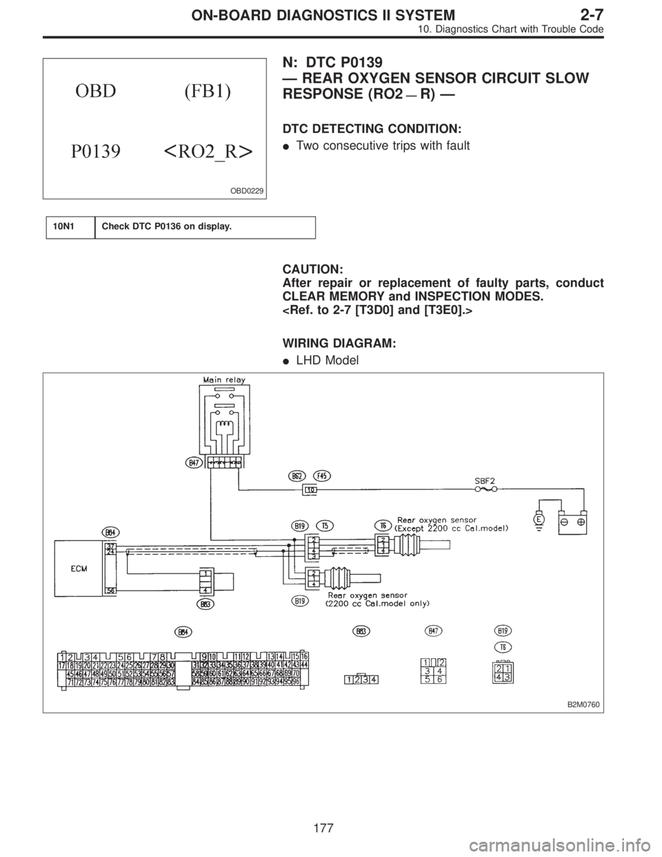
N: DTC P0139
—REAR OXYGEN SENSOR CIRCUIT SLOW
RESPONSE (RO2
—R)—
DTC DETECTING CONDITION:
�Two consecutive trips with fault
10N1Check DTC P0136 on display.
CAUTION:
After repair or replacement of faulty parts, conduct
CLEAR MEMORY and INSPECTION MODES.
WIRING DIAGRAM:
�LHD Model
B2M0760
177
2-7ON-BOARD DIAGNOSTICS II SYSTEM
10. Diagnostics Chart with Trouble Code
Page 2182 of 2890
 Designate mode using function key.
(6) Read data on Subaru select monitor.
Function mode: F09
SPECIFIED DATA:
0.5±0.2 V (Throttle fully closed.)
4.6±0.3 V (Throttle fully open.)
[Must be")
B3M0383
(5) Designate mode using function key.
(6) Read data on Subaru select monitor.
Function mode: F09
SPECIFIED DATA:
0.5±0.2 V (Throttle fully closed.)
4.6±0.3 V (Throttle fully open.)
[Must be changed correspondingly with accelera-
tor pedal operation (from“released”to
“depressed”position).]
B3M0238A
4. CHECK POWER SUPPLY TO THROTTLE POSITION
SENSOR.
1) Turn ignition switch to OFF.
2) Disconnect connector from throttle position sensor.
3) Turn ignition switch to ON.
4) Measure power supply voltage to throttle position sen-
sor.
Connector & terminal / Specified voltage:
(E13) No. 1—Body / 5.12±0.1 V
OBD0145A
�Using Subaru select monitor:
(1) Turn ignition switch to OFF.
(2) Connect the Subaru select monitor to data link con-
nector.
(3) Turn ignition switch to ON and Subaru select moni-
tor switch to ON.
OBD0506
(4) Designate mode using function key.
(5) Read data on Subaru select monitor.
Function mode: F14
SPECIFIED DATA:
5.12±0.1 V
42
3-2AUTOMATIC TRANSMISSION AND DIFFERENTIAL
7. Diagnostic Chart with Trouble Code
Page 2274 of 2890
B4M0440
B4M0441
1. CHECK RESISTANCE OF VALVE RELAY.
1) Turn ignition switch OFF.
2) Remove valve relay.
3) Measure resistance between valve relay terminals.
Terminal / Specified resistance:
No. A—B / 90±10Ω
B4M0442
2. CHECK CONTACT POINT OF VALVE RELAY.
1) Turn ignition switch OFF.
2) Remove valve relay.
3) Attach circuit tester probes to terminals as shown in
figure.
4) Measure resistance between respective terminals.
Terminal / Specified resistance:
No. C—E/1Ωor less (When 12 volts applied.)
No. C—E/1MΩor more
(When no voltage is applied.)
No. C—F/1MΩor more
(When 12 volts applied.)
No. C—F/1Ωor less
(When no voltage is applied.)
63
4-4bBRAKES
8. Diagnostics Chart with Trouble Code
Page 2373 of 2890
8B6CHECK POOR CONTACT IN CONNEC-
TOR BETWEEN ABSCM AND ABS SEN-
SOR.
: Is there poor contact in connectors between
ABSCM and ABS sensor?
: Repair connector.
: Go to step8B7.
8B7
CHECK ABSCM.
1) Connect all connectors.
2) Erase the memory.
3) Perform inspection mode.
4) Read out the trouble code.
: Is the same trouble code as in the current
diagnosis still being output?
: Replace ABSCM.
: Go to next.
: Are other trouble codes being output?
: Proceed with the diagnosis corresponding to the
trouble code.
: A temporary poor contact.
NOTE:
Check harness and connectors between ABSCM and ABS
sensor.
33
4-4cBRAKES [ABS 5.3 TYPE]
8. Diagnostics Chart with Trouble Code
Page 2381 of 2890
B4M1038A
8C9
CHECK SHIELD CIRCUIT.
1) Connect all connectors.
2) Measure resistance between shield connector and
chassis ground.
: Trouble code/Connector & terminal
22/(B100) No. 11—Chassis ground
24/(B100) No. 2—Chassis ground
26/(P1) No. 8—Chassis ground
28/(P1) No. 3—Chassis ground
Is resistance less than 0.5Ω?
: Go to step8C10.
: Repair shield harness.
8C10
CHECK ABSCM.
1) Connect all connectors.
2) Erase the memory.
3) Perform inspection mode.
4) Read out the trouble code.
: Is the same trouble code as in the current
diagnosis still being output?
: Replace ABSCM.
: Go to next.
: Are other trouble codes being output?
: Proceed with the diagnosis corresponding to the
trouble code.
: A temporary noise interference.
41
4-4cBRAKES [ABS 5.3 TYPE]
8. Diagnostics Chart with Trouble Code
Page 2386 of 2890
10) Remove disc rotor from hub.
: Is the ABS sensor pole piece or the tone
wheel contaminated by dirt or other foreign
matter?
: Thoroughly remove dirt or other foreign matter.
: Go to next.
: Are there broken or damaged teeth in the
ABS sensor pole piece or the tone wheel?
: Replace ABS sensor or tone wheel.
: Go to next step.
11) Measure hub runout.
: Is the runout less than 0.05 mm (0.0020 in)?
: Go to step8D4.
: Repair hub.
8D4
CHECK ABSCM.
1) Turn ignition switch to OFF.
2) Connect all connectors.
3) Erase the memory.
4) Perform inspection mode.
5) Read out the trouble code.
: Is the same trouble code as in the current
diagnosis still being output?
: Replace ABSCM.
: Go to next.
: Are other trouble codes being output?
: Proceed with the diagnosis corresponding to the
trouble code.
: A temporary poor contact.
46
4-4cBRAKES [ABS 5.3 TYPE]
8. Diagnostics Chart with Trouble Code
Page 2392 of 2890
 Connect connector to hydraulic unit.
2) Measure resistance between ABSCM connector termi-
nals.
: Trouble code/Connector & term")
B4M0829A
8E6CHECK HARNESS CONNECTOR
BETWEEN ABSCM AND HYDRAULIC
UNIT.
1) Connect connector to hydraulic unit.
2) Measure resistance between ABSCM connector termi-
nals.
: Trouble code/Connector & terminal
31/(F49) No. 30—No. 1
33/(F49) No. 24—No. 1
35/(F49) No. 23—No. 1
37/(F49) No. 31—No. 1
Is resistance 9.0±0.7Ω?
: Go to step8E7.
: Repair harness connector between ABSCM and
hydraulic unit.
8E7CHECK POOR CONTACT IN CONNEC-
TOR BETWEEN ABSCM AND HYDRAU-
LIC UNIT.
: Is there poor contact in connectors between
ABSCM and hydraulic unit?
: Repair connector.
: Go to step8E8.
8E8
CHECK ABSCM.
1) Connect all connectors.
2) Erase the memory.
3) Perform inspection mode.
4) Read out the trouble code.
: Is the same trouble code as in the current
diagnosis still being output?
: Replace ABSCM.
: Go to next.
: Are other trouble codes being output?
: Proceed with the diagnosis corresponding to the
trouble code.
: A temporary poor contact.
52
4-4cBRAKES [ABS 5.3 TYPE]
8. Diagnostics Chart with Trouble Code
Page 2398 of 2890
 Connect connector to hydraulic unit.
2) Measure resistance between ABSCM connector termi-
nals.
: Trouble code/Connector & term")
B4M0836A
8F6CHECK HARNESS CONNECTOR
BETWEEN ABSCM AND HYDRAULIC
UNIT.
1) Connect connector to hydraulic unit.
2) Measure resistance between ABSCM connector termi-
nals.
: Trouble code/Connector & terminal
32/(F49) No. 3—No. 1
34/(F49) No. 51—No. 1
36/(F49) No. 50—No. 1
38/(F49) No. 4—No. 1
Is resistance 4.8±0.5Ω?
: Go to step8F7.
: Repair harness connector between ABSCM and
hydraulic unit.
8F7CHECK POOR CONTACT IN CONNEC-
TOR BETWEEN ABSCM AND HYDRAU-
LIC UNIT.
: Is there poor contact in connectors between
ABSCM and hydraulic unit?
: Repair connector.
: Go to step8F8.
8F8
CHECK ABSCM.
1) Connect all connectors.
2) Erase the memory.
3) Perform inspection mode.
4) Read out the trouble code.
: Is the same trouble code as in the current
diagnosis still being output?
: Replace ABSCM.
: Go to next.
: Are other trouble codes being output?
: Proceed with the diagnosis corresponding to the
trouble code.
: A temporary poor contact.
58
4-4cBRAKES [ABS 5.3 TYPE]
8. Diagnostics Chart with Trouble Code
 Turn ignition switch OFF.
2) Remove valve relay.
3) Measure resistance between valve relay terminals.
Terminal / Specified resistance:
No. A—B")
 Connec")
 Connect all connectors.
2) Measure resistance between shield connector and
chassis ground.
: Trouble code/Connector & terminal
22/(B100) No. 11—Chassis ground
2")
 Remove disc rotor from hub.
: Is the ABS sensor pole piece or the tone
wheel contaminated by dirt or other foreign
matter?
: Thoroughly remove dirt or other foreign matter.
: Go to next.
: Are the")