Page 1668 of 2890
B6M0238
3) Unfasten holddown clip which secures harness, and
disconnect connectors from body harness.
4) Move combination switch to respective positions and
check continuity between terminals as indicated in the fol-
lowing tables:
Lighting switch
Terminal
Switch positionc-1 c-2 c-3
OFF
Tail��
*��
Head���
Parking switch
Terminal
Switch positionc-10 c-11 c-9
OFF��
*XX
ON��
Dimmer and passing switch
Terminal
Switch positiona-3 a-2 a-1 a-4
Flash��
�
*���
Low beam��
*���
HI-beam��
G6M0111
2. HEADLIGHT RELAY
Check continuity between terminals as indicated in table
below, when connecting the battery to terminal No. 1 and
No. 3.
When current flows.Between terminals
No. 2 and No. 4Continuity exists.
When current does not flow.Between terminals
No. 2 and No. 4Continuity does not
exist.
Between terminals
No. 1 and No. 3Continuity exists.
12
6-2SERVICE PROCEDURE
4. Headlight
Page 1675 of 2890
B: DISASSEMBLY AND ASSEMBLY
1. COMBINATION SWITCH
Refer to 6-2 [W4C1] as for disassembly and assembly of
combination switch.
C: INSPECTION
1. COMBINATION SWITCH (ON-CAR)
1) Remove instrument panel lower cover.
2) Remove lower column cover.
B6M0238
3) Unfasten holddown clip which secures harness, and
disconnect connectors from body harness.
4) Move combination switch to respective positions and
check continuity between terminals as indicated in table
below:
Turn signal switch
Terminal
Switch positiona-5 a-7 a-6
TurnL⋅L′��
*xx
N
*xx
R⋅R′��
B6M0344
2. HAZARD SWITCH
Move hazard switch to each position and check continuity
between terminals as indicated in table below:
73910561 2
ON��
�����
OFF����
19
6-2SERVICE PROCEDURE
6. Turn Signal and Hazard Warning Light
Page 1804 of 2890
B2M0636
3) Ensure freeze frame data(s) is (are) shown.
(1) When no trouble is detected, or after memory is
cleared.
B2M0636
(2) When a trouble occurs but the corresponding item
is not displayed.
B2M0638
(3) When only one trouble corresponding to the dis-
played item has occurred.
�
1Abbreviation
�
2Diagnostic trouble code of trouble occurred
B2M0649
(4) When multiple troubles corresponding to the dis-
played item are detected.
NOTE:
Freeze frame data is shown on display for 2 seconds at a
time.
36
2-7ON-BOARD DIAGNOSTICS II SYSTEM
3. Diagnosis System
Page 1808 of 2890
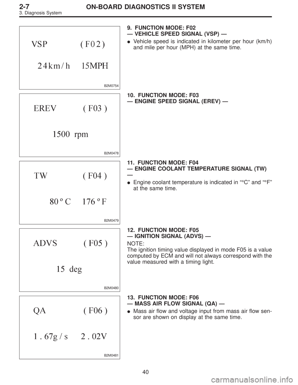
B2M0754
9. FUNCTION MODE: F02
—VEHICLE SPEED SIGNAL (VSP)—
�Vehicle speed is indicated in kilometer per hour (km/h)
and mile per hour (MPH) at the same time.
B2M0478
10. FUNCTION MODE: F03
—ENGINE SPEED SIGNAL (EREV)—
B2M0479
11. FUNCTION MODE: F04
—ENGINE COOLANT TEMPERATURE SIGNAL (TW)
—
�Engine coolant temperature is indicated in“°C”and“°F”
at the same time.
B2M0480
12. FUNCTION MODE: F05
—IGNITION SIGNAL (ADVS)—
NOTE:
The ignition timing value displayed in mode F05 is a value
computed by ECM and will not always correspond with the
value measured with a timing light.
B2M0481
13. FUNCTION MODE: F06
—MASS AIR FLOW SIGNAL (QA)—
�Mass air flow and voltage input from mass air flow sen-
sor are shown on display at the same time.
40
2-7ON-BOARD DIAGNOSTICS II SYSTEM
3. Diagnosis System
Page 1815 of 2890

LED No. Signal name Display
1——
2——
3 Neutral switch NT
4——
5——
6——
7 Test mode connector UD
8 Identification of AT model AT
9 Ignition switch IG
0——
——NT——
—UD AT IG—
1
2345
67890
41. FUNCTION MODE: FA0
—ON↔OFF SIGNAL—
Requirement for LED“ON”.
LED No. 3�On MT model, gear position is in neutral.
�On AT model, shift position is in“P”or“N”.
LED No. 7 Test mode connector is connected.
LED No. 8 Vehicle is AT model.
LED No. 9 Ignition switch is turned ON.
LED No. Signal name Display
1 Radiator fan relay 2 R2
2 Knock signal KS
3Purge control solenoid
valveCN
4 Fuel pump relay FP
5——
6 Radiator fan relay 1 R1
7 A/C relay AR
8 A/C switch AC
9——
0——
R2 KS CN FP—
R1 AR AC——
1
2345
67890
42. FUNCTION MODE: FA1
—ON↔OFF SIGNAL—
Requirement for LED“ON”.
LED No. 1 Radiator fan relay 2 is turned ON.
LED No. 2 Engine is knocking.
LED No. 3 Purge control solenoid valve is in function.
LED No. 4 Fuel pump relay is turned ON.
LED No. 6 Radiator fan relay 1 is turned ON.
LED No. 7 A/C relay is turned ON.
LED No. 8 A/C switch is turned ON.
NOTE:
�When LED No. 1, 3, 4, 6 and 7 blinks with the test mode
connector connected and the ignition switch turned to ON,
the corresponding part is functioning properly.
�When LED No. 4 illuminates for only 2 seconds after the
ignition switch is turned to ON, (and then goes out), the
corresponding part is functioning properly.
47
2-7ON-BOARD DIAGNOSTICS II SYSTEM
3. Diagnosis System
Page 1817 of 2890

LED No. Signal name Display
1 Catalyst CA
2 EGR system E1
3California model
identification signalFC
4——
5——
6——
7——
8 Rear oxygen sensor signal OR
9 Front oxygen sensor signal O2
0——
CA E1 FC——
——OR O2—
1
2345
67890
45. FUNCTION MODE: FA4
—ON↔OFF SIGNAL—
Requirement for LED“ON”.
LED No. 1 Diagnosis of catalyzer is finished.
LED No. 2 Diagnosis of EGR system is finished.
LED No. 3 Vehicle is except California model.
LED No. 8 Rear oxygen sensor mixture ratio is rich.
LED No. 9 Front oxygen sensor mixture ratio is rich.
LED No. Signal name Display
1——
2——
3——
4——
5——
6 Vent control solenoid valve AL
7 EGR solenoid valve ER
8Pressure control solenoid
valvePC
9——
0——
—————
AL ER PC——
1
2345
67890
46. FUNCTION MODE: FA5
—ON↔OFF SIGNAL—
Requirement for LED“ON”.
LED No. 6 Vent control solenoid valve is in function.
LED No. 7 EGR solenoid valve is in function.
LED No. 8 Pressure control solenoid valve is in func-
tion.
NOTE:
When LED No. 6, 7 and 8 blinks with the test mode con-
nector connected and the ignition switch turned to ON, the
corresponding part is functioning properly.
49
2-7ON-BOARD DIAGNOSTICS II SYSTEM
3. Diagnosis System
Page 1891 of 2890
 LIST
DTC
No.Abbreviation
(Subaru select monitor)Item Page
P0100 QA Mass air flow sensor circuit malfunction 125
P0101 QA
—R M")
10. Diagnostics Chart with Trouble
Code
A: DIAGNOSTIC TROUBLE CODE (DTC) LIST
DTC
No.Abbreviation
(Subaru select monitor)Item Page
P0100 QA Mass air flow sensor circuit malfunction 125
P0101 QA
—R Mass air flow sensor circuit range/performance problem 132
P0105 P
—S Pressure sensor circuit malfunction 134
P0106 PS
—R Pressure sensor circuit range/performance problem 142
P0115 TW Engine coolant temperature sensor circuit malfunction 147
P0120 THV Throttle position sensor circuit malfunction 151
P0121 TH
—R Throttle position sensor circuit range/performance problem 157
P0125 TW
—CL Insufficient coolant temperature for closed loop fuel control 159
P0130 FO2
—V Front oxygen sensor circuit malfunction 161
P0133 FO2
—R Front oxygen sensor circuit slow response 164
P0135 FO2H Front oxygen sensor heater circuit malfunction 166
P0136 RO2
—V Rear oxygen sensor circuit malfunction 172
P0139 RO2
—R Rear oxygen sensor circuit slow response 177
P0141 RO2H Rear oxygen sensor heater circuit malfunction 179
P0170 FUEL Fuel trim malfunction 185
P0180 TNKT Fuel temperature sensor A circuit malfunction 190
P0181 TNKT
—F Fuel temperature sensor A circuit range/performance problem 195
P0201 INJ1 Fuel injector circuit malfunction - #1
197 P0202 INJ2 Fuel injector circuit malfunction - #2
P0203 INJ3 Fuel injector circuit malfunction - #3
P0204 INJ4 Fuel injector circuit malfunction - #4
P0301 MIS
—1 Cylinder 1 misfire detected
203 P0302 MIS
—2 Cylinder 2 misfire detected
P0303 MIS
—3 Cylinder 3 misfire detected
P0304 MIS
—4 Cylinder 4 misfire detected
P0325 KNOCK Knock sensor circuit malfunction 211
P0335 CRANK Crankshaft position sensor circuit malfunction 215
P0340 CAM Camshaft position sensor circuit malfunction 218
P0400 EGR Exhaust gas recirculation flow malfunction 221
P0403 EGRSOL Exhaust gas recirculation circuit malfunction 227
P0420 CAT Catalyst system efficiency below threshold 233
P0440 EVAP Evaporative emission control system malfunction 236
P0441 CPC
—F Evaporative emission control system incorrect purge flow 241
P0443 CPC Evaporative emission control system purge control valve circuit malfunction 244
P0446 VCMSOL Evaporative emission control system vent control malfunction 249
P0450 TNKP Evaporative emission control system pressure sensor malfunction 255
P0451 TNKP
—F Evaporative emission control system pressure sensor range/performance problem 264
123
2-7ON-BOARD DIAGNOSTICS II SYSTEM
10. Diagnostics Chart with Trouble Code
Page 1932 of 2890
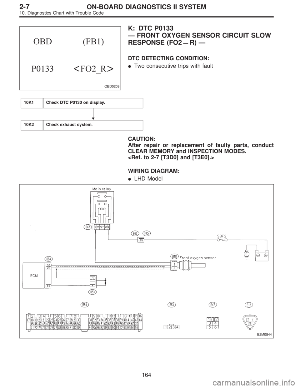
OBD0209
K: DTC P0133
—FRONT OXYGEN SENSOR CIRCUIT SLOW
RESPONSE (FO2
—R)—
DTC DETECTING CONDITION:
�Two consecutive trips with fault
10K1Check DTC P0130 on display.
10K2Check exhaust system.
CAUTION:
After repair or replacement of faulty parts, conduct
CLEAR MEMORY and INSPECTION MODES.
WIRING DIAGRAM:
�LHD Model
B2M0544
�
164
2-7ON-BOARD DIAGNOSTICS II SYSTEM
10. Diagnostics Chart with Trouble Code
 Unfasten holddown clip which secures harness, and
disconnect connectors from body harness.
4) Move combination switch to respective positions and
check continuity between terminals as indic")
![SUBARU LEGACY 1996 Service Repair Manual B: DISASSEMBLY AND ASSEMBLY
1. COMBINATION SWITCH
Refer to 6-2 [W4C1] as for disassembly and assembly of
combination switch.
C: INSPECTION
1. COMBINATION SWITCH (ON-CAR)
1) Remove instrument panel low](/manual-img/17/57433/w960_57433-1674.png "SUBARU LEGACY 1996 Service Repair Manual B: DISASSEMBLY AND ASSEMBLY
1. COMBINATION SWITCH
Refer to 6-2 [W4C1] as for disassembly and assembly of
combination switch.
C: INSPECTION
1. COMBINATION SWITCH (ON-CAR)
1) Remove instrument panel low")
 Ensure freeze frame data(s) is (are) shown.
(1) When no trouble is detected, or after memory is
cleared.
B2M0636
(2) When a trouble occurs but the corresponding item
is not displayed.
B2M06")