Page 924 of 2890

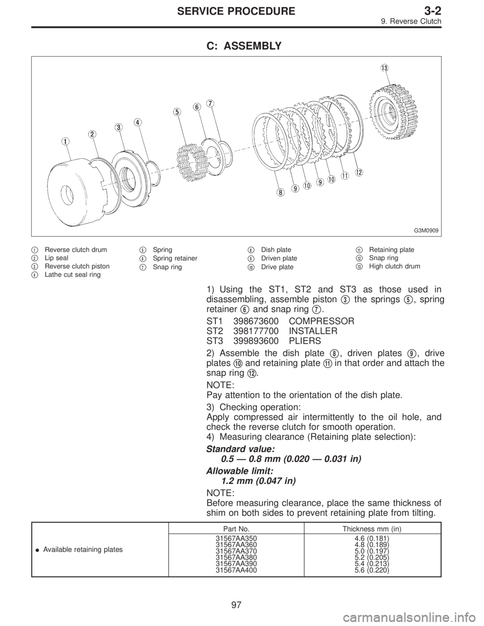
C: ASSEMBLY
G3M0909
�1Reverse clutch drum
�
2Lip seal
�
3Reverse clutch piston
�
4Lathe cut seal ring�
5Spring
�
6Spring retainer
�
7Snap ring�
8Dish plate
�
9Driven plate
�
10Drive plate�
11Retaining plate
�
12Snap ring
�
13High clutch drum
1) Using the ST1, ST2 and ST3 as those used in
disassembling, assemble piston�
3the springs�5, spring
retainer�
6and snap ring�7.
ST1 398673600 COMPRESSOR
ST2 398177700 INSTALLER
ST3 399893600 PLIERS
2) Assemble the dish plate�
8, driven plates�9, drive
plates�
10and retaining plate�11in that order and attach the
snap ring�
12.
NOTE:
Pay attention to the orientation of the dish plate.
3) Checking operation:
Apply compressed air intermittently to the oil hole, and
check the reverse clutch for smooth operation.
4) Measuring clearance (Retaining plate selection):
Standard value:
0.5—0.8 mm (0.020—0.031 in)
Allowable limit:
1.2 mm (0.047 in)
NOTE:
Before measuring clearance, place the same thickness of
shim on both sides to prevent retaining plate from tilting.
�Available retaining platesPart No. Thickness mm (in)
31567AA350
31567AA360
31567AA370
31567AA380
31567AA390
31567AA4004.6 (0.181)
4.8 (0.189)
5.0 (0.197)
5.2 (0.205)
5.4 (0.213)
5.6 (0.220)
97
3-2SERVICE PROCEDURE
9. Reverse Clutch
Page 927 of 2890
�Available retaining platesPart No. Thickness mm (in)
31567AA190
31567AA200
31567AA210
31567AA220
31567AA230
31567AA240
31567AA250
31567AA2603.6 (0.142)
3.8 (0.150)
4.0 (0.157)
4.2 (0.165)
4.4 (0.173)
4.6 (0.181)
4.8 (0.189)
5.0 (0.197)
G3M0471
11. Forward Clutch Drum
A: DISASSEMBLY
1) Remove two snap rings from the forward clutch drum.
2) Remove the retaining plate, drive plates, driven plates
and dish plate. (Forward clutch)
G3M0472
3) Remove the snap ring from the forward clutch drum.
4) Remove the retaining plate, drive plates, driven plates
and dish plate. (Overrunning clutch)
G3M0473
5) Compress the spring retainer, and remove the snap ring
from the forward clutch, by using ST1 and ST2.
ST1 498627100 SEAT
ST2 398673600 COMPRESSOR
G3M0474
6) Install the one-way clutch inner race to the forward
clutch drum, and apply compressed air to remove the over-
running piston and forward piston.
100
3-2SERVICE PROCEDURE
10. High Clutch - 11. Forward Clutch Drum
Page 928 of 2890
�Available retaining platesPart No. Thickness mm (in)
31567AA190
31567AA200
31567AA210
31567AA220
31567AA230
31567AA240
31567AA250
31567AA2603.6 (0.142)
3.8 (0.150)
4.0 (0.157)
4.2 (0.165)
4.4 (0.173)
4.6 (0.181)
4.8 (0.189)
5.0 (0.197)
G3M0471
11. Forward Clutch Drum
A: DISASSEMBLY
1) Remove two snap rings from the forward clutch drum.
2) Remove the retaining plate, drive plates, driven plates
and dish plate. (Forward clutch)
G3M0472
3) Remove the snap ring from the forward clutch drum.
4) Remove the retaining plate, drive plates, driven plates
and dish plate. (Overrunning clutch)
G3M0473
5) Compress the spring retainer, and remove the snap ring
from the forward clutch, by using ST1 and ST2.
ST1 498627100 SEAT
ST2 398673600 COMPRESSOR
G3M0474
6) Install the one-way clutch inner race to the forward
clutch drum, and apply compressed air to remove the over-
running piston and forward piston.
100
3-2SERVICE PROCEDURE
10. High Clutch - 11. Forward Clutch Drum
Page 940 of 2890
G3M0501
3) Install the driven plates, drive plates, and pressure
plate, and secure with a snap ring with ST1, ST2 and a
press.
ST1 398673600 COMPRESSOR
ST2 498627000 SEAT
G3M0502
4) Apply compressed air to see if the assembled parts
move smoothly.
G3M0503
5) Check the clearance.
Standard value:
0.2—0.6 mm (0.008—0.024 in)
Allowable limit:
1.6 mm (0.063 in)
If the clearance is not within the specified range, select a
proper pressure plate.
NOTE:
Before measuring clearance, place the same thickness of
shim on both sides to prevent pressure plate from tilting.
�Available pressure platesPart No. Thickness mm (in)
31593AA151
31593AA161
31593AA171
31593AA1813.3 (0.130)
3.7 (0.146)
4.1 (0.161)
4.5 (0.177)
G3M0505
6) Press-fit the ball bearing with ST.
ST 899580100 INSTALLER
111
3-2SERVICE PROCEDURE
15. Transfer Clutch
Page 1011 of 2890
Left side Right side
Camber is increased.
B4M0190
Rotate
counterclockwise.
B4M0350
Rotate clockwise.
Camber is decreased.
B4M0350
Rotate clockwise.
B4M0190
Rotate
counterclockwise.
3) Tighten the two self-locking nuts.
Tightening torque:
152±20 N⋅m (15.5±2.0 kg-m, 112±14 ft-lb)
M4A0059
3. FRONT WHEEL TOE-IN
�Inspection
1) Using a toe gauge, measure front wheel toe-in.
Toe-in: 0±3 mm (0±0.12 in)
2) Mark rear sides of left and right tires at height corre-
sponding to center of spindles and measure distance“B”
between marks.
3) Move vehicle forward so that marks line up with front
sides at height corresponding to center of spindles.
4) Measure distance“A”between left and right marks.
Toe-in can then be obtained by the following equation:
B�A = Toe-in
10
4-1SERVICE PROCEDURE
1. On-car Services
Page 1012 of 2890

G4M0482
�Adjustment
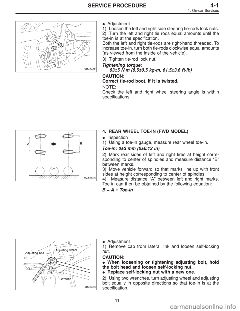
1) Loosen the left and right side steering tie-rods lock nuts.
2) Turn the left and right tie rods equal amounts until the
toe-in is at the specification.
Both the left and right tie-rods are right-hand threaded. To
increase toe-in, turn both tie-rods clockwise equal amounts
(as viewed from the inside of the vehicle).
3) Tighten tie-rod lock nut.
Tightening torque:
83±5 N⋅m (8.5±0.5 kg-m, 61.5±3.6 ft-lb)
CAUTION:
Correct tie-rod boot, if it is twisted.
NOTE:
Check the left and right wheel steering angle is within
specifications.
M4A0059
4. REAR WHEEL TOE-IN (FWD MODEL)
�Inspection
1) Using a toe-in gauge, measure rear wheel toe-in.
Toe-in: 0±3 mm (0±0.12 in)
2) Mark rear sides of left and right tires at height corre-
sponding to center of spindles and measure distance“B”
between marks.
3) Move vehicle forward so that marks line up with front
sides at height corresponding to center of spindles.
4) Measure distance“A”between left and right marks.
Toe-in can then be obtained by the following equation:
B�A = Toe-in
G4M0483
�Adjustment
1) Remove cap from lateral link and loosen self-locking
nut.
CAUTION:
�When loosening or tightening adjusting bolt, hold
the bolt head and loosen self-locking nut.
�Replace self-locking nut with a new one.
2) Using two wrenches, turn adjusting wheel and adjusting
bolt equally in opposite directions so that toe-in is at the
specification.
11
4-1SERVICE PROCEDURE
1. On-car Services
Page 1013 of 2890

Left side Right side
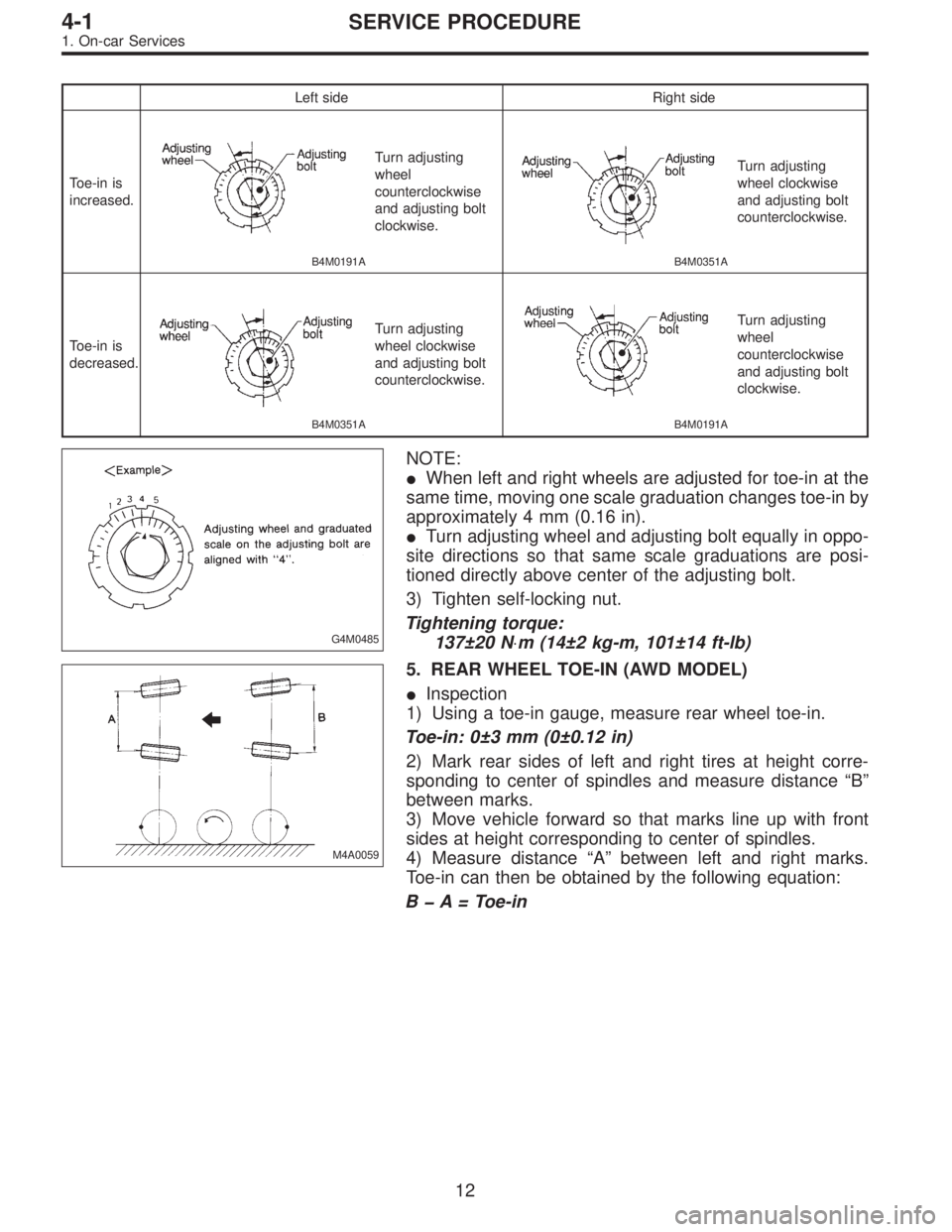
Toe-in is
increased.
B4M0191A
Turn adjusting
wheel
counterclockwise
and adjusting bolt
clockwise.
B4M0351A
Turn adjusting
wheel clockwise
and adjusting bolt
counterclockwise.
Toe-in is
decreased.
B4M0351A
Turn adjusting
wheel clockwise
and adjusting bolt
counterclockwise.
B4M0191A
Turn adjusting
wheel
counterclockwise
and adjusting bolt
clockwise.
G4M0485
NOTE:
�When left and right wheels are adjusted for toe-in at the
same time, moving one scale graduation changes toe-in by
approximately 4 mm (0.16 in).
�Turn adjusting wheel and adjusting bolt equally in oppo-
site directions so that same scale graduations are posi-
tioned directly above center of the adjusting bolt.
3) Tighten self-locking nut.
Tightening torque:
137±20 N⋅m (14±2 kg-m, 101±14 ft-lb)
M4A0059
5. REAR WHEEL TOE-IN (AWD MODEL)
�Inspection
1) Using a toe-in gauge, measure rear wheel toe-in.
Toe-in: 0±3 mm (0±0.12 in)
2) Mark rear sides of left and right tires at height corre-
sponding to center of spindles and measure distance“B”
between marks.
3) Move vehicle forward so that marks line up with front
sides at height corresponding to center of spindles.
4) Measure distance“A”between left and right marks.
Toe-in can then be obtained by the following equation:
B�A = Toe-in
12
4-1SERVICE PROCEDURE
1. On-car Services
Page 1108 of 2890

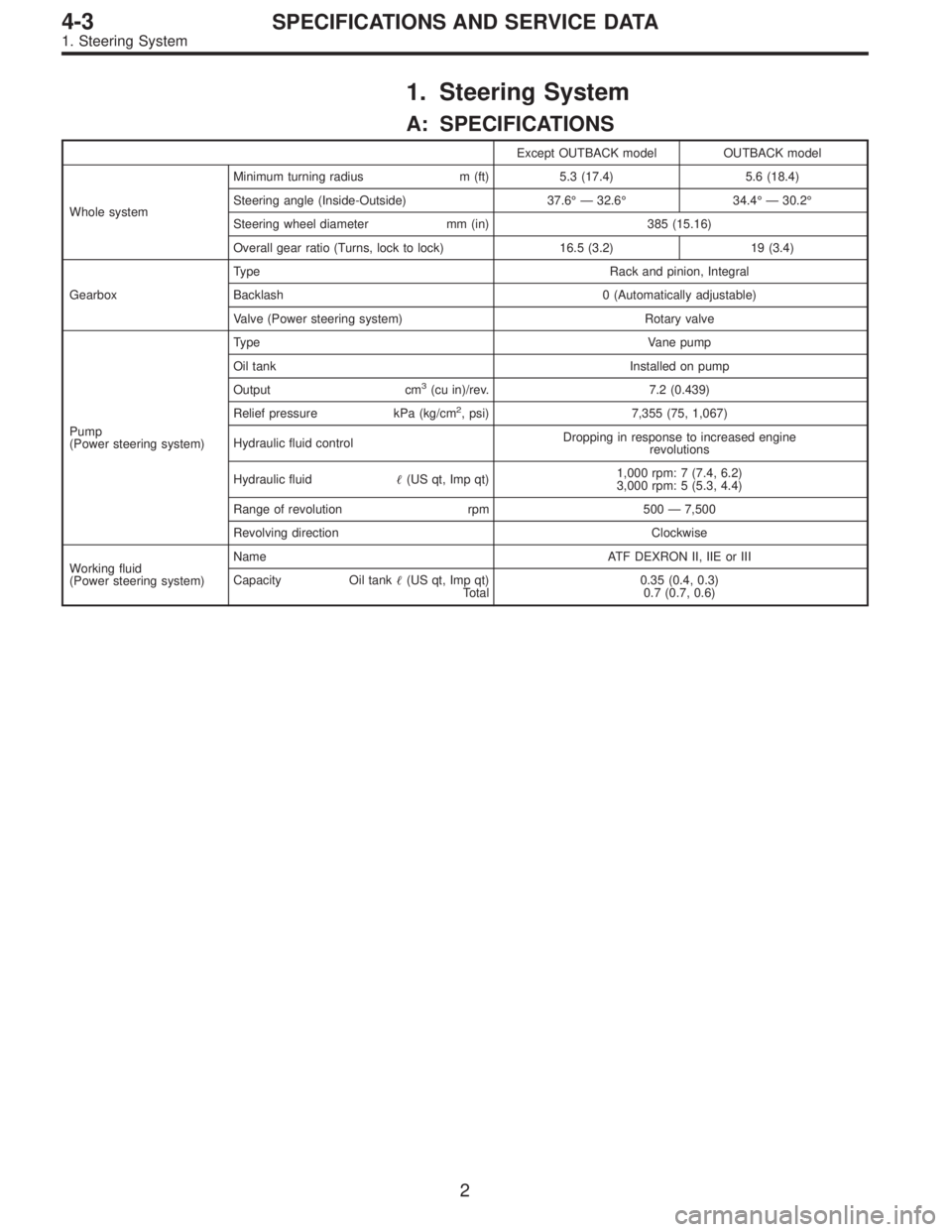
1. Steering System
A: SPECIFICATIONS
Except OUTBACK model OUTBACK model
Whole systemMinimum turning radius m (ft) 5.3 (17.4) 5.6 (18.4)
Steering angle (Inside-Outside) 37.6°—32.6°34.4°—30.2°
Steering wheel diameter mm (in) 385 (15.16)
Overall gear ratio (Turns, lock to lock) 16.5 (3.2) 19 (3.4)
GearboxType Rack and pinion, Integral
Backlash 0 (Automatically adjustable)
Valve (Power steering system) Rotary valve
Pump
(Power steering system)Type Vane pump
Oil tank Installed on pump
Output cm
3(cu in)/rev. 7.2 (0.439)
Relief pressure kPa (kg/cm
2, psi) 7,355 (75, 1,067)
Hydraulic fluid controlDropping in response to increased engine
revolutions
Hydraulic fluid�(US qt, Imp qt)1,000 rpm: 7 (7.4, 6.2)
3,000 rpm: 5 (5.3, 4.4)
Range of revolution rpm 500—7,500
Revolving direction Clockwise
Working fluid
(Power steering system)Name ATF DEXRON II, IIE or III
Capacity Oil tank�(US qt, Imp qt)
Total0.35 (0.4, 0.3)
0.7 (0.7, 0.6)
2
4-3SPECIFICATIONS AND SERVICE DATA
1. Steering System