Page 426 of 2890
G2M0761
2. VALVE SEAT
Inspect intake and exhaust valve seats, and correct the
contact surfaces with valve seat cutter if they are defective
or when valve guides are replaced.
Valve seat width: W
Intake
Standard
1.0 mm (0.039 in)
Limit
1.7 mm (0.067 in)
Exhaust
Standard
1.5 mm (0.059 in)
Limit
2.2 mm (0.087 in)
3. VALVE GUIDE
1) Check the clearance between valve guide and stem.
The clearance can be checked by measuring the outside
diameter of valve stem and the inside diameter of valve
guide with outside and inside micrometers respectively.
Clearance between the valve guide and valve stem:
Standard
Intake
0.035—0.062 mm (0.0014—0.0024 in)
Exhaust
0.040—0.067 mm (0.0016—0.0026 in)
Limit
0.15 mm (0.0059 in)
Valve guide inner diameter:
6.000—6.015 mm (0.2362—0.2368 in)
Valve stem outer diameter:
Intake
5.950—5.965 mm (0.2343—0.2348 in)
Exhaust
5.950—5.965 mm (0.2343—0.2348 in)
38
2-3bSERVICE PROCEDURE
4. Cylinder Head
Page 444 of 2890
C: INSPECTION
1. CYLINDER BLOCK
1) Check for cracks and damage visually. Especially,
inspect important parts by means of red lead check.
2) Check the oil passages for clogging.
3) Inspect crankcase surface that mates with cylinder
head for warping by using a straight edge, and correct by
grinding if necessary.
Warping limit:
0.05 mm (0.0020 in)
Grinding limit:
0.1 mm (0.004 in)
Standard height of cylinder block:
201.0 mm (7.91 in)
B2M0082A
2. CYLINDER AND PISTON
1) The cylinder bore size is stamped on the cylinder
block’s front upper surface.
NOTE:
Standard sized pistons are classified into two grades,“A”
and“B”. These grades should be used as a guide line in
selecting a standard piston.
Standard diameter:
A: 99.505—99.515 mm (3.9175—3.9179 in)
B: 99.495—99.505 mm (3.9171—3.9175 in)
56
2-3bSERVICE PROCEDURE
5. Cylinder Block
Page 454 of 2890
B2M0707A
4) Installation of piston rings and oil ring
(1) Install oil ring spacer, upper rail and lower rail in this
order by hand. Then install second ring and top ring
with a piston ring expander.
(2) Position the top ring gap at A or B in the Figure.
(3) Position the second ring gap at 180°on the reverse
side for the top ring gap.
B2M0708A
(4) Position the upper rail gap at C or D in the Figure.
(5) Position the expander gap the at 180°of the
reverse side for the upper rail gap.
(6) Position the lower rail gap at E or F in the Figure.
CAUTION:
�Ensure ring gaps do not face the same direction.
�Ensure ring gaps are not within the piston skirt area.
G2M0183
5) Install circlip.
Install circlips in piston holes located opposite service
holes in cylinder block, when positioning all pistons in the
corresponding cylinders.
CAUTION:
Use new circlips.
66
2-3bSERVICE PROCEDURE
5. Cylinder Block
Page 538 of 2890
G2M0411
5) Remove front oxygen sensor.
CAUTION:
When removing oxygen sensor, do not force oxygen
sensor especially when exhaust pipe is cold, other-
wise it will damage exhaust pipe.
G2M0412
B: INSTALLATION
1) Before installing front oxygen sensor, apply anti-seize
compound only to threaded portion of front oxygen sensor
to make the next removal easier.
Anti-seize compound:
SS-30 by JET LUBE
CAUTION:
Never apply anti-seize compound to protector of front
oxygen sensor.
G2M0411
2) Install front oxygen sensor.
Tightening torque:
21±3 N⋅m (2.1±0.3 kg-m, 15.2±2.2 ft-lb)
3) Lower the vehicle.
4) Connect connector of front oxygen sensor.
5) Install air intake duct.
20
2-7SERVICE PROCEDURE
7. Front Oxygen Sensor
Page 539 of 2890
B2M0335
8. Rear Oxygen Sensor
A: REMOVAL
1. EXCEPT CALIFORNIA 2200 cc MODEL
1) Lift-up the vehicle.
2) Disconnect connector from rear oxygen sensor.
3) Apply SUBARU CRC or its equivalent to threaded por-
tion of rear oxygen sensor, and leave it for one minute or
more.
SUBARU CRC (Part No. 004301003)
B2M0351
4) Remove rear oxygen sensor.
CAUTION:
When removing rear oxygen sensor, do not force rear
oxygen sensor especially when exhaust pipe is cold,
otherwise it will damage exhaust pipe.
B2M0740
2. CALIFORNIA 2200 cc MODEL
1) Disconnect connector from rear oxygen sensor.
2) Lift-up the vehicle.
3) Apply SUBARU CRC or its equivalent to threaded por-
tion of rear oxygen sensor, and leave it for one minute or
more.
SUBARU CRC (Part No. 004301003)
21
2-7SERVICE PROCEDURE
8. Rear Oxygen Sensor
Page 540 of 2890

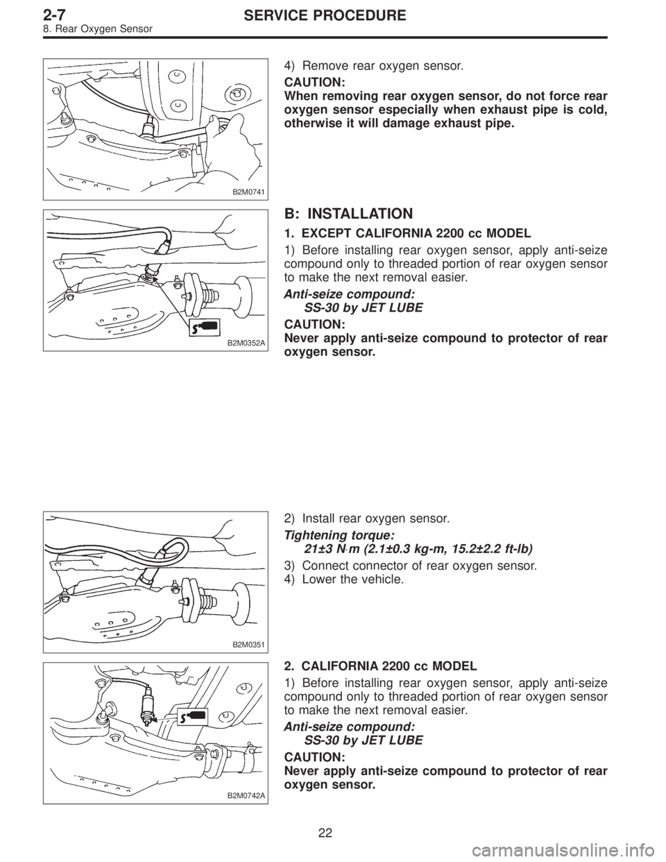
B2M0741
4) Remove rear oxygen sensor.
CAUTION:
When removing rear oxygen sensor, do not force rear
oxygen sensor especially when exhaust pipe is cold,
otherwise it will damage exhaust pipe.
B2M0352A
B: INSTALLATION
1. EXCEPT CALIFORNIA 2200 cc MODEL
1) Before installing rear oxygen sensor, apply anti-seize
compound only to threaded portion of rear oxygen sensor
to make the next removal easier.
Anti-seize compound:
SS-30 by JET LUBE
CAUTION:
Never apply anti-seize compound to protector of rear
oxygen sensor.
B2M0351
2) Install rear oxygen sensor.
Tightening torque:
21±3 N⋅m (2.1±0.3 kg-m, 15.2±2.2 ft-lb)
3) Connect connector of rear oxygen sensor.
4) Lower the vehicle.
B2M0742A
2. CALIFORNIA 2200 cc MODEL
1) Before installing rear oxygen sensor, apply anti-seize
compound only to threaded portion of rear oxygen sensor
to make the next removal easier.
Anti-seize compound:
SS-30 by JET LUBE
CAUTION:
Never apply anti-seize compound to protector of rear
oxygen sensor.
22
2-7SERVICE PROCEDURE
8. Rear Oxygen Sensor
Page 576 of 2890

1. Fuel System
Trouble and possible cause Corrective action
1. Insufficient fuel supply to the injector
1) Fuel pump will not operate.
�Defective terminal contact.Inspect connections, especially ground, and tighten
securely.
�Trouble in electromagnetic or electronic circuit parts. Replace fuel pump.
2) Lowering of fuel pump function. Replace fuel pump.
3) Clogged dust or water in the fuel filter. Replace fuel filter, clean or replace fuel tank.
4) Clogged or bent fuel pipe or hose. Clean, correct or replace fuel pipe or hose.
5) Air is mixed in the fuel system. Inspect or retighten each connection part.
6) Clogged or bent breather tube or pipe. Clean, correct or replace air breather tube or pipe.
7) Damaged diaphragm of pressure regulator. Replace.
2. Leakage or blow out fuel
1) Loosened joints of the fuel pipe. Retightening.
2) Cracked fuel pipe, hose and fuel tank. Replace.
3) Defective welding part on the fuel tank. Replace.
4) Defective drain packing of the fuel tank. Replace.
5) Clogged or bent air breather tube or air vent tube. Clean, correct or replace air breather tube or air vent tube.
3. Gasoline smell inside of compartment
1)Loose joints at air breather tube, air vent tube and fuel filler
pipe.Retightening.
2) Defective packing air tightness on the fuel saucer. Correct or replace packing.
3) Cracked fuel separator. Replace separator.
4. Defective fuel meter indicator
1) Defective operation of fuel meter unit. Replace.
2) Defective operation of fuel meter. Replace.
5. Noise
1) Large operation noise or vibration of fuel pump. Replace.
NOTE:
When the vehicle is left unattended for an extended period of time, water may accumulate in the fuel
tank.
�To prevent water condensation:
1) Top off the fuel tank or drain the fuel completely.
2) Drain water condensation from the fuel filter.
�Refilling the fuel tank:
Refill the fuel tank while there is still some fuel left in the tank.
�Protecting the fuel system against freezing and water condensation:
1) Cold areas
In snow-covered areas, mountainous areas, skiing areas, etc. where ambient temperatures drop
below 0°C (32°F) throughout the winter season, use an anti-freeze solution in the cooling system.
Refueling will also complement the effect of anti-freeze solution each time the fuel level drops to about
one-half. After the winter season, drain water which may have accumulated in the fuel filter and fuel
tank in the manner same as that described under affected areas as below.
2) Affected areas
When water condensation is notched in the fuel filter, drain water from both the fuel filter and fuel tank
or use a water removing agent (or anti-freeze solution) in the fuel tank.
�Observe the instructions, notes, etc., indicated on the label affixed to the anti-freeze solution (water
removing agent) container before use.
27
2-8DIAGNOSTICS
1. Fuel System
Page 643 of 2890
G2M0411
5) Remove front oxygen sensor.
CAUTION:
When removing oxygen sensor, do not force oxygen
sensor especially when exhaust pipe is cold, other-
wise it will damage exhaust pipe.
G2M0412
B: INSTALLATION
1) Before installing front oxygen sensor, apply anti-seize
compound only to threaded portion of front oxygen sensor
to make the next removal easier.
Anti-seize compound:
SS-30 by JET LUBE
CAUTION:
Never apply anti-seize compound to protector of front
oxygen sensor.
G2M0411
2) Install front oxygen sensor.
Tightening torque:
21±3 N⋅m (2.1±0.3 kg-m, 15.2±2.2 ft-lb)
3) Lower the vehicle.
4) Connect connector of front oxygen sensor.
5) Install air intake duct.
20
2-7SERVICE PROCEDURE
7. Front Oxygen Sensor