Page 1148 of 2890

2. OIL LEAK CHECK PROCEDURE AND
REPLACEMENT PARTS
NOTE:
Parts requiring replacement are described in the smallest
unit of spare parts including damaged parts and spare
parts damaged. In actual disassembly work, accidental
damage as well as inevitable damage to some related
parts must be taken into account, and spare parts for them
must also be prepared. However, it is essential to pinpoint
the cause of trouble, and limit the number of replacement
parts as much as possible.
1) Leakage from“a”
The oil seal is damaged. Replace valve assembly with a
new one.
2) Leakage from“b”
The torsion bar O-ring is damaged. Replace valve assem-
bly with a new one.
3) Leakage from“c”
The oil seal is damaged. Replace valve assembly with a
new one.
4) Leakage from“d”
The pipe is damaged. Replace the faulty pipe or O-ring.
5) If leak is other than a, b, c, or d, and if oil is leaking from
the gearbox, move the right and left boots toward tie-rod
end side, respectively, with the gearbox mounted to the
vehicle, and remove oil from the surrounding portions.
Then, turn the steering wheel from lock to lock 30 to 40
times with the engine running, then make comparison of
the leaked portion immediately after and several hours
after this operation.
6) Leakage from“e”
The cylinder seal is damaged. Replace rack bush with a
new one.
7) Leakage from“f”
There are two possible causes. Take following step first.
Remove the pipe assembly B from the valve housing, and
close the circuit with ST.
ST 926420000 PLUG
Turn the steering wheel from lock to lock 30 to 40 times
with the engine running, then make comparison of the
leaked portion between immediately after and several
hours after this operation.
CAUTION:
�If leakage from“f”is noted again:
The oil seal of pinion and valve assembly is damaged.
Replace pinion and valve assembly with a new one. Or
replace the oil seal and the parts that are damaged
during disassembly with new ones.
�If oil stops leaking from“f”:
The oil seal of rack housing is damaged.
Replace the oil seal and the parts that are damaged
during disassembly with new ones.
41
4-3SERVICE PROCEDURE
5. Control Valve (Power Steering Gearbox) [LHD model]
Page 1157 of 2890

2. OIL LEAK CHECK PROCEDURE AND
REPLACEMENT PARTS
NOTE:
Parts requiring replacement are described in the smallest
unit of spare parts including damaged parts and spare
parts damaged. In actual disassembly work, accidental
damage as well as inevitable damage to some related
parts must be taken into account, and spare parts for them
must also be prepared. However, it is essential to pinpoint
the cause of trouble, and limit the number of replacement
parts as much as possible.
1) Leakage from“a”
The oil seal is damaged. Replace valve assembly with a
new one.
2) Leakage from“b”
The torsion bar O-ring is damaged. Replace valve assem-
bly with a new one.
3) Leakage from“c”
The oil seal is damaged. Replace valve assembly with a
new one.
4) Leakage from“d”
The pipe is damaged. Replace the faulty pipe or O-ring.
5) If leak is other than a, b, c, or d, and if oil is leaking from
the gearbox, move the right and left boots toward tie-rod
end side, respectively, with the gearbox mounted to the
vehicle, and remove oil from the surrounding portions.
Then, turn the steering wheel from lock to lock 30 to 40
times with the engine running, then make comparison of
the leaked portion immediately after and several hours
after this operation.
6) Leakage from“e”
There are two possible causes. Take following step first.
Remove the pipe assembly B from the valve housing, and
close the circuit with ST.
ST 926420000 PLUG
Turn the steering wheel from lock to lock 30 to 40 times
with the engine running, then make comparison of the
leaked portion between immediately after and several
hours after this operation.
CAUTION:
�If leakage from“e”is noted again:
The oil seal of pinion and valve assembly is damaged.
Replace pinion and valve assembly with a new one. Or
replace the oil seal and the parts that are damaged
during disassembly with new ones.
�If oil stops leaking from“e”:
The oil seal of rack housing is damaged.
Replace the oil seal and the parts that are damaged
during disassembly with new ones.
50
4-3SERVICE PROCEDURE
6. Control Valve (Power Steering Gearbox) [RHD model]
Page 1208 of 2890
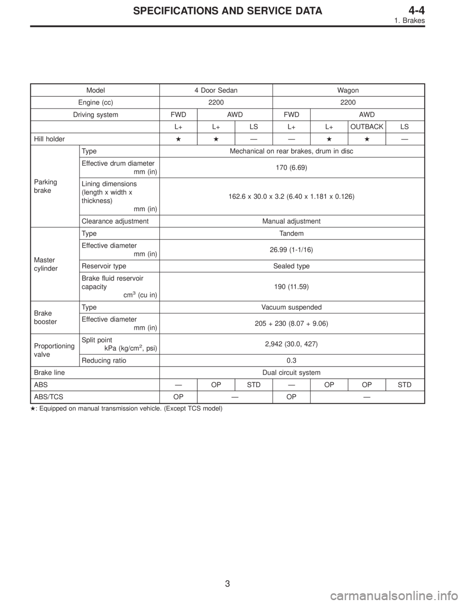
Model 4 Door Sedan Wagon
Engine (cc) 2200 2200
Driving system FWD AWD FWD AWD
L+ L+ LS L+ L+ OUTBACK LS
Hill holder��——��—
Parking
brakeType Mechanical on rear brakes, drum in disc
Effective drum diameter
mm (in)170 (6.69)
Lining dimensions
(length x width x
thickness)
mm (in)162.6 x 30.0 x 3.2 (6.40 x 1.181 x 0.126)
Clearance adjustment Manual adjustment
Master
cylinderType Tandem
Effective diameter
mm (in)26.99 (1-1/16)
Reservoir type Sealed type
Brake fluid reservoir
capacity
cm
3(cu in)190 (11.59)
Brake
boosterType Vacuum suspended
Effective diameter
mm (in)205 + 230 (8.07 + 9.06)
Proportioning
valveSplit point
kPa (kg/cm
2, psi)2,942 (30.0, 427)
Reducing ratio 0.3
Brake line Dual circuit system
ABS—OP STD—OP OP STD
ABS/TCS OP—OP—
�: Equipped on manual transmission vehicle. (Except TCS model)
3
4-4SPECIFICATIONS AND SERVICE DATA
1. Brakes
Page 1210 of 2890
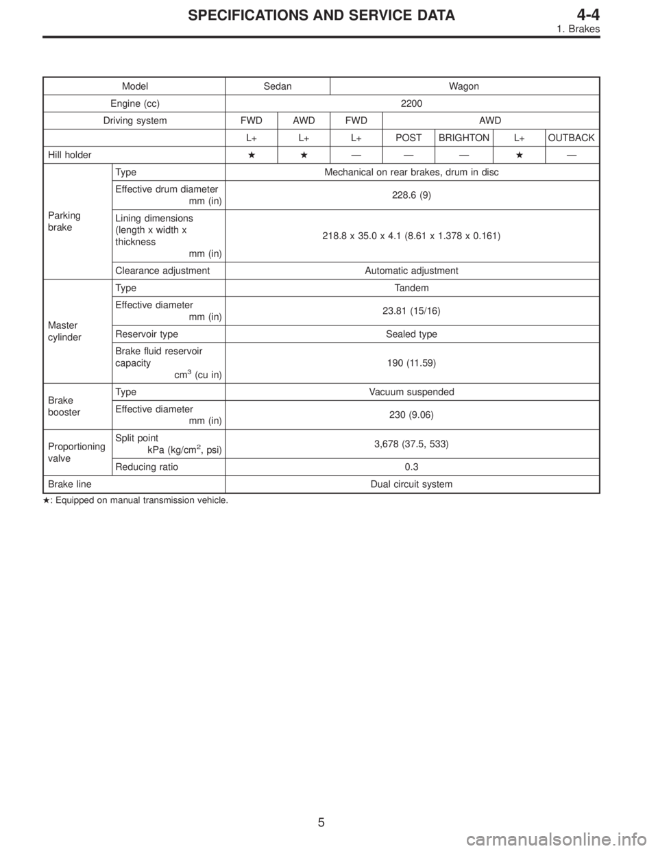
Model Sedan Wagon
Engine (cc) 2200
Driving system FWD AWD FWD AWD
L+ L+ L+ POST BRIGHTON L+ OUTBACK
Hill holder��—— —�—
Parking
brakeType Mechanical on rear brakes, drum in disc
Effective drum diameter
mm (in)228.6 (9)
Lining dimensions
(length x width x
thickness
mm (in)218.8 x 35.0 x 4.1 (8.61 x 1.378 x 0.161)
Clearance adjustment Automatic adjustment
Master
cylinderType Tandem
Effective diameter
mm (in)23.81 (15/16)
Reservoir type Sealed type
Brake fluid reservoir
capacity
cm
3(cu in)190 (11.59)
Brake
boosterType Vacuum suspended
Effective diameter
mm (in)230 (9.06)
Proportioning
valveSplit point
kPa (kg/cm
2, psi)3,678 (37.5, 533)
Reducing ratio 0.3
Brake line Dual circuit system
�: Equipped on manual transmission vehicle.
5
4-4SPECIFICATIONS AND SERVICE DATA
1. Brakes
Page 1212 of 2890
Model Sedan Wagon
Engine (cc) 2500 2200 2500
Driving system AWD
GT LSi GT LSi OUTBACK* OUTBACK*
Hill holder————STD—
Parking
brakeType Mechanical on rear brakes, drum in disc
Effective drum diameter
mm (in)170 (6.69)
Lining dimensions
(length x width x
thickness)
mm (in)162.6 x 30.0 x 3.2 (6.40 x 1.181 x 0.126)
Clearance adjustment Manual adjustment
Master
cylinderType Tandem
Effective diameter
mm (in)26.99 (1-1/16)
Reservoir type Sealed type
Brake fluid reservoir
capacity
cm
3(cu in)190 (11.59)
Brake
boosterType Vacuum suspended
Effective diameter
mm (in)205 + 230 (8.07 + 9.06)
Propor-
tioning
valveSplit point
kPa (kg/cm
2, psi)3,678 (37.5, 533)
Reducing ratio 0.3
Brake line Dual circuit system
ABSSTD
*: Step roof model
7
4-4SPECIFICATIONS AND SERVICE DATA
1. Brakes
Page 1619 of 2890
G6M0095
1. Starter
A: REMOVAL AND INSTALLATION
1) Disconnect battery ground cable.
G2M0309
2) Disconnect connector and terminal from starter.
3) Remove starter from transmission.
4) Installation is in the reverse order of removal.
Tightening torque:
50±4 N⋅m (5.1±0.4 kg-m, 36.9±2.9 ft-lb)
B: TEST
1. MAGNETIC SWITCH
CAUTION:
�The following magnetic switch tests should be per-
formed with specified voltage applied.
�Each test should be conducted within 3 to 5 sec-
onds. Power to be furnished should be one-half the
rated voltage.
B6M0415A
1) Pull-in test
Connect two battery negative leads onto magnetic switch
body and terminal C respectively. Then connect battery
positive lead onto terminal 50. Pinion should extend when
lead connections are made.
B6M0416A
2) Holding-in test
Disconnect lead from terminal C with pinion extended. Pin-
ion should be held in the extended position.
6
6-1SERVICE PROCEDURE
1. Starter
Page 1620 of 2890
 Return test
Connect two battery negative leads onto terminal 50 and
onto switch body respectively. Then connect battery posi-
tive lead onto terminal C. Next, disconnect lead from ter-
min")
B6M0417A
3) Return test
Connect two battery negative leads onto terminal 50 and
onto switch body respectively. Then connect battery posi-
tive lead onto terminal C. Next, disconnect lead from ter-
minal 50. Pinion should return immediately.
2. PERFORMANCE TEST
The starter is required to produce a large torque and high
rotating speed, but these starter characteristics vary with
the capacity of the battery. It is therefore important to use
a battery with the specified capacity whenever testing the
starter.
The starter should be checked for the following three items:
1. No-load test
Measure the maximum rotating speed and current under a
no-load state.
2. Load test
Measure the magnitude of current needed to generate the
specified torque and rotating speed.
3. Stall test
Measure the torque and current when the armature is
locked.
B6M0418A
1) No-load test
Run single starter under no-load state, and measure its
rotating speed, voltage, and current, using the specified
battery. Measured values must meet the following stan-
dards:
No-load test (Standard):
Voltage/Current
11 V/90 A, or more
Rotating speed
TN128000-8311: 3,000 rpm, or more
TN128000-8321: 3,350 rpm, or more
7
6-1SERVICE PROCEDURE
1. Starter
Page 1659 of 2890
 External parts
Check for the existence of dirt or cracks on the battery
case, top cover, vent plugs, and terminal posts. If
necessary, clean with water and wipe with a dry")
B: INSPECTION
1. BATTERY
1) External parts
Check for the existence of dirt or cracks on the battery
case, top cover, vent plugs, and terminal posts. If
necessary, clean with water and wipe with a dry cloth.
Apply a thin coat of grease on the terminal posts to prevent
corrosion.
2) Electrolyte level
Check the electrolyte level in each cell. If the level is below
MIN LEVEL, bring the level to MAX LEVEL by pouring dis-
tilled water into the battery cell. Do not fill beyond MAX
LEVEL.
WARNING:
�Electrolyte has toxicity; be careful handling the
fluid.
�Avoid contact with skin, eyes or clothing. Especially
at contact with eyes, blush with water for 15 minutes
and get prompt medical attention.
�Batteries produce explosive gasses. Keep sparks,
flame, cigarettes away.
�Ventilate when charging or using in enclosed space.
�For safety, in case an explosion does occur, wear
eye protection or shield your eyes when working near
any battery. Never lean over a battery.
�Do not let battery fluid contact eyes, skin, fabrics, or
paint-work because battery fluid is corrosive acid.
�To lessen the risk of sparks, remove rings, metal
watch-bands, and other metal jewelry. Never allow
metal tools to contact the positive battery terminal and
anything connected to it while you are at the same time
in contact with any other metallic portion of the vehicle
because a short circuit will be caused.
5
6-2SERVICE PROCEDURE
2. Battery
 2500 2200 2500
Driving system AWD
GT LSi GT LSi OUTBACK* OUTBACK*
Hill holder————STD—
Parking
brakeType Mechanical on rear brakes, drum in disc
Effective drum d")
 Disconnect battery ground cable.
G2M0309
2) Disconnect connector and terminal from starter.
3) Remove starter from transmission.
4) Installation is in")