Page 1296 of 2890
 Slowly depress the brake pedal and keep it
depressed. Then, open the air bleeder to discharge air
together with the fluid.
Release air bleeder for 1 to 2 seconds.
Next, with the bleeder closed, sl")
(2) Slowly depress the brake pedal and keep it
depressed. Then, open the air bleeder to discharge air
together with the fluid.
Release air bleeder for 1 to 2 seconds.
Next, with the bleeder closed, slowly release the brake
pedal.
Repeat these steps until there are no more air bubbles
in the vinyl tube.
Allow 3 to 4 seconds between two brake pedal opera-
tions.
CAUTION:
Cover bleeder with waste cloth, when loosening it, to
prevent brake fluid from being splashed over sur-
rounding parts.
NOTE:
Brake pedal operating must be very slow.
4) Bleed air from suction pipe through front RH caliper.
(1) Open the air bleeder.
(2) Keep pressing TCS OFF switch for 20 seconds or
more.
NOTE:
Ensure no air comes out from air bleeder.
(3) Close the air bleeder.
5) Bleed air through front LH caliper by operating brake
pedal. This is the same procedure as step 3).
6) Bleed air from suction pipe through front LH caliper.
This is the same procedure as step 4).
7) Bleed air through front RH and LH calipers by operat-
ing brake pedal. This is the same procedure as step 3).
Repeat steps 3) to 7) until air does no longer comes out.
8) Tighten air bleeders securely when bubbles are visible.
Air bleeder tightening torque:
8±1 N⋅m (0.8±0.1 kg-m, 5.8±0.7 ft-lb)
9) Bleed air through rear LH and RH caliper by operating
brake pedal. This is the same procedure as step 3).
10) Tighten air bleeders securely when bubbles are vis-
ible.
Air bleeder tightening torque:
8±1 N⋅m (0.8±0.1 kg-m, 5.8±0.7 ft-lb)
87
4-4SERVICE PROCEDURE
19. Air Bleeding (With TCS model)
Page 1302 of 2890
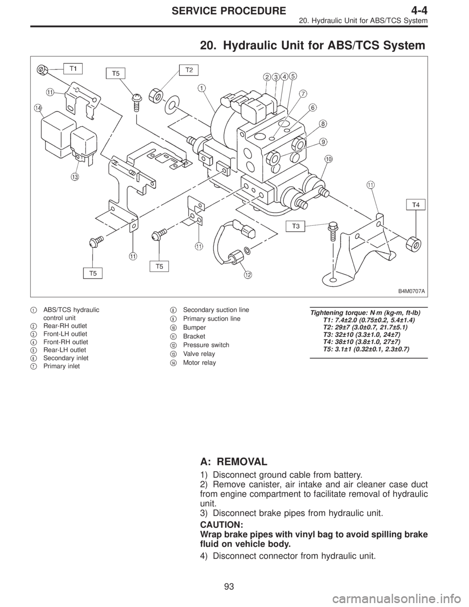
20. Hydraulic Unit for ABS/TCS System
B4M0707A
�1ABS/TCS hydraulic
control unit
�
2Rear-RH outlet
�
3Front-LH outlet
�
4Front-RH outlet
�
5Rear-LH outlet
�
6Secondary inlet
�
7Primary inlet�
8Secondary suction line
�
9Primary suction line
�
10Bumper
�
11Bracket
�
12Pressure switch
�
13Valve relay
�
14Motor relay
Tightening torque: N⋅m (kg-m, ft-lb)
T1: 7.4±2.0 (0.75±0.2, 5.4±1.4)
T2: 29±7 (3.0±0.7, 21.7±5.1)
T3: 32±10 (3.3±1.0, 24±7)
T4: 38±10 (3.8±1.0, 27±7)
T5: 3.1±1 (0.32±0.1, 2.3±0.7)
A: REMOVAL
1) Disconnect ground cable from battery.
2) Remove canister, air intake and air cleaner case duct
from engine compartment to facilitate removal of hydraulic
unit.
3) Disconnect brake pipes from hydraulic unit.
CAUTION:
Wrap brake pipes with vinyl bag to avoid spilling brake
fluid on vehicle body.
4) Disconnect connector from hydraulic unit.
93
4-4SERVICE PROCEDURE
20. Hydraulic Unit for ABS/TCS System
Page 1316 of 2890
B4M0628
G: INSTALLATION
1) Install hydraulic unit and bracket.
Tightening torque:
32±7 N⋅m (3.3±0.7 kg-m, 23.9±5.1 ft-lb)
2) Connect brake pipes to their correct hydraulic unit con-
nections.
3) Connect connector to hydraulic unit.
4) Install canister.
5) Install air cleaner case.
6) Install air intake duct.
7) Connect ground cable to battery.
CAUTION:
Cover relay securely with rubber boot.
21. ABS/TCS Control Module
A: REMOVAL
1) Disconnect ground cable from battery.
2) Remove floor mat located under lower right side of front
seat.
B4M0643A
3) Remove screw which secure ABS/TCS control module
from the body.
4) Disconnect connector from ABS/TCS control module.
B: INSPECTION
Check that connector is connected correctly and that con-
nector terminal sliding resistance is correct.
107
4-4SERVICE PROCEDURE
20. Hydraulic Unit for ABS/TCS System - 21. ABS/TCS Control Module
Page 1317 of 2890
B4M0628
G: INSTALLATION
1) Install hydraulic unit and bracket.
Tightening torque:
32±7 N⋅m (3.3±0.7 kg-m, 23.9±5.1 ft-lb)
2) Connect brake pipes to their correct hydraulic unit con-
nections.
3) Connect connector to hydraulic unit.
4) Install canister.
5) Install air cleaner case.
6) Install air intake duct.
7) Connect ground cable to battery.
CAUTION:
Cover relay securely with rubber boot.
21. ABS/TCS Control Module
A: REMOVAL
1) Disconnect ground cable from battery.
2) Remove floor mat located under lower right side of front
seat.
B4M0643A
3) Remove screw which secure ABS/TCS control module
from the body.
4) Disconnect connector from ABS/TCS control module.
B: INSPECTION
Check that connector is connected correctly and that con-
nector terminal sliding resistance is correct.
107
4-4SERVICE PROCEDURE
20. Hydraulic Unit for ABS/TCS System - 21. ABS/TCS Control Module
Page 1319 of 2890
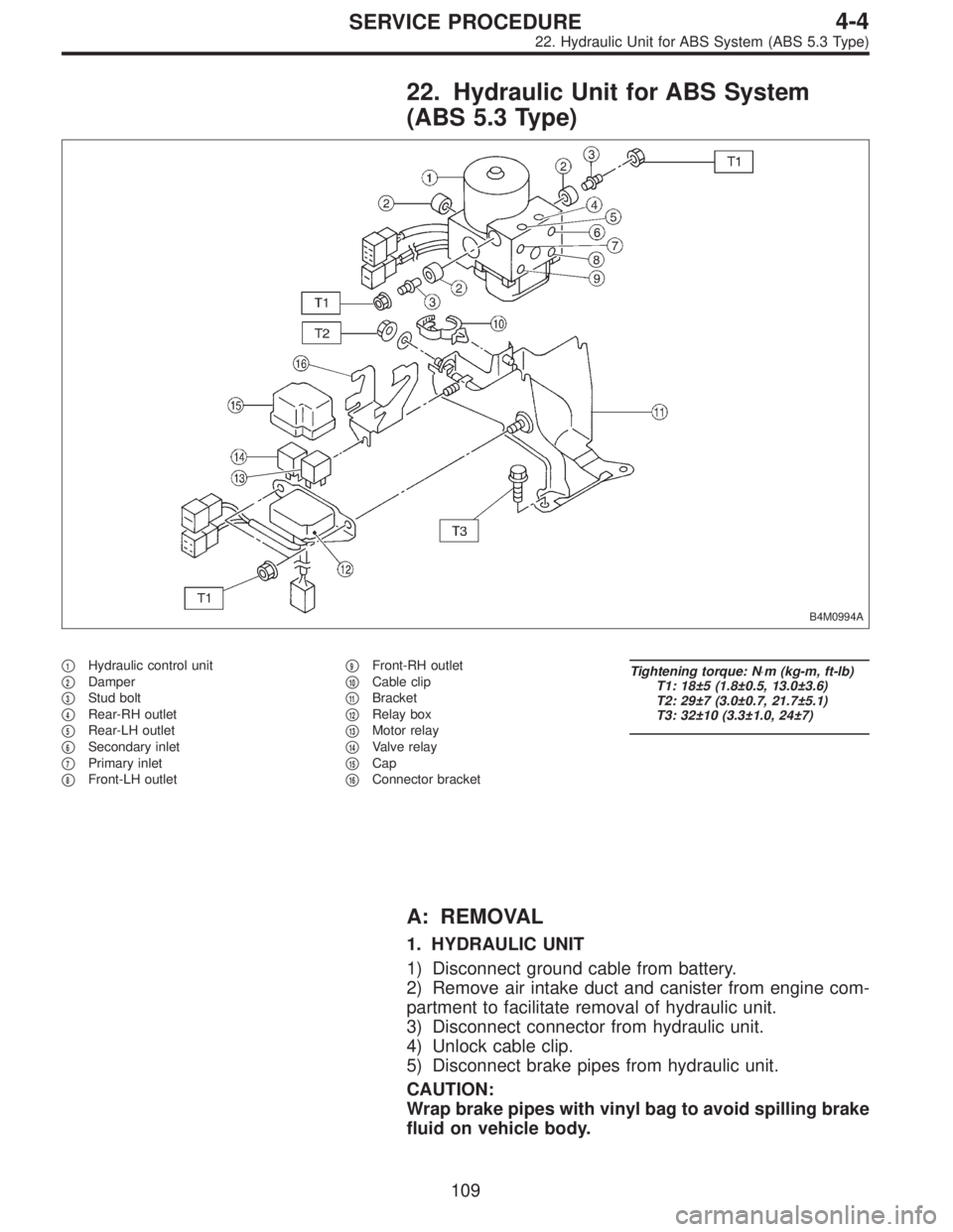
22. Hydraulic Unit for ABS System
(ABS 5.3 Type)
B4M0994A
�1Hydraulic control unit
�
2Damper
�
3Stud bolt
�
4Rear-RH outlet
�
5Rear-LH outlet
�
6Secondary inlet
�
7Primary inlet
�
8Front-LH outlet�
9Front-RH outlet
�
10Cable clip
�
11Bracket
�
12Relay box
�
13Motor relay
�
14Valve relay
�
15Cap
�
16Connector bracket
Tightening torque: N⋅m (kg-m, ft-lb)
T1: 18±5 (1.8±0.5, 13.0±3.6)
T2: 29±7 (3.0±0.7, 21.7±5.1)
T3: 32±10 (3.3±1.0, 24±7)
A: REMOVAL
1. HYDRAULIC UNIT
1) Disconnect ground cable from battery.
2) Remove air intake duct and canister from engine com-
partment to facilitate removal of hydraulic unit.
3) Disconnect connector from hydraulic unit.
4) Unlock cable clip.
5) Disconnect brake pipes from hydraulic unit.
CAUTION:
Wrap brake pipes with vinyl bag to avoid spilling brake
fluid on vehicle body.
109
4-4SERVICE PROCEDURE
22. Hydraulic Unit for ABS System (ABS 5.3 Type)
Page 1328 of 2890
B4M0996
E: INSTALLATION
1. HYDRAULIC UNIT
1) Install hydraulic unit.
Tightening torque:
18±5 N⋅m (1.8±0.5 kg-m, 13.0±3.6 ft-lb)
2) Connect hydraulic unit ground cable to body.
Tightening torque:
32±10 N⋅m (3.3±1.0 kg-m, 24±7 ft-lb)
3) Connect brake pipes to their correct hydraulic unit con-
nections.
B4M1031A
4) Secure hydraulic unit connector to connector bracket.
CAUTION:
Align connector with mating receptacle.
5) Using cable clip, secure hydraulic unit harness to relay
box harness.
CAUTION:
Make sure hydraulic unit harness band is secured
beneath cable clip.
6) Connect connector to hydraulic unit.
7) Install canister.
8) Install air intake duct.
9) Connect ground cable to battery.
10) Bleed air from the brake system.
B4M1029
2. RELAY BOX
1) Install relay box and connector bracket.
Tightening torque:
18±5 N⋅m (1.8±0.5 kg-m, 13.0±3.6 ft-lb)
11 8
4-4SERVICE PROCEDURE
22. Hydraulic Unit for ABS System (ABS 5.3 Type)
Page 1335 of 2890
 Fluid leakage from the hydraulic mechanismRepair or replace (cup, piston seal, piston boot, master cylin")
1. Entire Brake System
Trouble and possible cause Corrective action
1. Insufficient braking
(1) Fluid leakage from the hydraulic mechanismRepair or replace (cup, piston seal, piston boot, master cylinder
piston kit, pipe or hose).
(2) Entry of air into the hydraulic mechanism Bleed the air.
(3) Excessively wide shoe clearance Adjust the clearance.
(4) Wear, deteriorated surface material, adhering water or fluid
on the liningReplace, grind or clean.
(5) Improper operation of master cylinder, disc caliper, brake
booster or check valveCorrect or replace.
2. Unstable or uneven braking
(1) Fluid on the lining, drum or rotor Eliminate cause of fluid leakage, clean, or replace.
(2) Drum or rotor eccentricity Correct or replace the drum or rotor.
(3) Worn brake drum, or damage to the drum caused by sand Correct by grinding, or replace.
(4) Improper lining contact, deteriorated surface material,
improper inferior material, or wearCorrect by grinding, or replace.
(5) Deformed back plate Correct or replace.
(6) Improper tire inflation Inflate to correct pressure.
(7) Disordered wheel alignment Adjust alignment.
(8) Loosened back plate or the support installing bolts Retighten.
(9) Loosened wheel bearing Retighten to normal tightening torque or replace.
(10) Trouble in the hydraulic system Replace the cylinder, brake pipe or hose.
(11) Uneven effect of the parking brake Check, adjust, or replace the rear brake and cable system.
3. Excessive pedal stroke
(1) Entry of air into the hydraulic mechanism Bleed the air.
(2) Excessive play in the master cylinder push rod Adjust.
(3) Fluid leakage from the hydraulic mechanismRepair or replace (cup, piston seal, piston boot, master cylinder
piston kit, pipe or hose).
(4) Improperly adjusted shoe clearance Adjust.
(5) Improper lining contact or worn lining Correct or replace.
124
4-4DIAGNOSTICS
1. Entire Brake System
Page 1336 of 2890
 Insufficient pedal play Adjust play.
(2) Improper master cylinder return Clean or replace the cylinder.
(3)")
Trouble and possible cause Corrective action
4. Brake dragging or improper brake return
(1) Insufficient pedal play Adjust play.
(2) Improper master cylinder return Clean or replace the cylinder.
(3) Clogged hydraulic system Replace.
(4) Improper return or adjustment of parking brake Correct or adjust.
(5) Weakened spring tension or breakage of shoe return spring Replace the spring.
(6) Excessively narrow shoe clearance Adjust the clearance.
(7) Improper disc caliper operation Correct or replace.
(8) Improper adjusted wheel bearing Adjust or replace.
5. Brake noise (1) (creak sound)
(1) Hardened or deteriorated lining Replace the shoe assembly or pad.
(2) Worn lining Replace the shoe assembly or pad.
(3) Loosened back plate or the support installing bolts Retighten.
(4) Loose wheel bearing Retighten to normal tightening torque.
(5) Dirty drum or rotor Clean the drum or rotor, or clean and replace the brake assembly.
6. Brake noise (2) (hissing sound)
(1) Worn lining Replace the shoe assembly or pad.
(2) Improper installed shoe or pad Correct or replace the shoe assembly or pad.
(3) Loose or bent drum or rotor Retighten or replace.
7. Brake noise (3) (click sound)
In the case of the disc brake:
(1) Excessively worn pad or the support Replace the pad or the support.
In the case of the drum brake:
(1) Excessively worn shoe ridge Replace the back plate.
(2) Lack of oil on the shoe ridge surface and anchor Add more grease.
125
4-4DIAGNOSTICS
1. Entire Brake System
 Install hydraulic unit and bracket.
Tightening torque:
32±7 N⋅m (3.3±0.7 kg-m, 23.9±5.1 ft-lb)
2) Connect brake pipes to their correct hydraulic unit con-
nections. <Re")
 Install hydraulic unit and bracket.
Tightening torque:
32±7 N⋅m (3.3±0.7 kg-m, 23.9±5.1 ft-lb)
2) Connect brake pipes to their correct hydraulic unit con-
nections. <Re")
 Install hydraulic unit.
Tightening torque:
18±5 N⋅m (1.8±0.5 kg-m, 13.0±3.6 ft-lb)
2) Connect hydraulic unit ground cable to body.
Tightening torque:")