Page 1388 of 2890
 Avoid unnecessary handling and contact of O-rings with
your hands, since even clea")
4. O-ring Connections
1. GENERAL
The following points should be kept in mind when assem-
bling O-ring connections.
1) Avoid unnecessary handling and contact of O-rings with
your hands, since even clean fingers contain body acids,
which can contaminate the O-ring surface.
2) Do not handle O-rings with gloves, shop towels, etc.,
since lint particles may cling to the O-ring, possibly caus-
ing a leak upon assembly.
3) Always lubricate O-rings before assembly to allow the
O-ring to seat itself properly.
4) Be certain to use torque wrenches when tightening
O-ring fittings, because overtightening can not only dam-
age the O-ring, but it can distort the tube end as well.
G4M0581
2. REMOVE PROTECTIVE SEALS
Just prior to making the connection, remove the protective
seals.
CAUTION:
If for any reason you have to stop before making a
connection, recap the tube, component or fitting.
G4M0582
Visually inspect the O-ring surface, the O-ring mating
surface, the threads and the connection points. If a defec-
tive part is found, replace it.
The O-ring must sit square against the tube bead. If
necessary, slide the O-ring into proper positionwith clean
hands.
15
4-7SERVICE PROCEDURE
4. O-ring Connections
Page 1389 of 2890

G4M0583
3. LUBRICATE THE COMPONENTS
For lubrication of the components, use only refrigerant oil
as described in the appropriate service manual. Apply oil
from an oil squirt gun or other closed container. Do not use
your finger to spread the oil over the O-ring.
Apply a small amount of refrigerant oil to the top and sides
of the O-ring. The area covered by oil should include the
O-ring and the tube bead.
G4M0584
4. TORQUE THE FITTING
Using a back-up wrench in conjunction with a calibrated
torque wrench, torque the connection to the midrange of
the specification.
After completion of torquing, use a clean shop towel to
remove any excess oil from the connection or any oil that
may have dripped on the vehicle body or other parts.
CAUTION:
If a leak is suspected after torquing, do not retighten
or retorque the connection. Instead, disassemble the
connection, remove the O-ring, and inspect the O-ring,
threads, joints and seating surfaces.
16
4-7SERVICE PROCEDURE
4. O-ring Connections
Page 1413 of 2890
 Disconnect the connection between the expansion
valve and pipe from receiver drier.
4) Remove the expansion valve from pipes.
5) To install expansion valve, reverse removal procedures.
Pro")
B4M0101A
3) Disconnect the connection between the expansion
valve and pipe from receiver drier.
4) Remove the expansion valve from pipes.
5) To install expansion valve, reverse removal procedures.
Properly wrap capillary tube of expansion valve with seal.
6) Check to see if the evaporator fins are clogged. If they
are, clean them with compressed air.
CAUTION:
Water must never be used to clean the evaporator.
7) Check parts that have been removed for cracks or
scratches, and repair or replace them with new ones, if
necessary.
8) Reassemble the evaporator in the reverse order of dis-
assembly.
NOTE:
Confirm that the O-ring is inserted in the specified position.
B4M0102A
15. Condenser Fan Assembly
A: REMOVAL AND INSTALLATION
1) Disconnect battery negative terminal.
2) Disconnect harness connector from fan motor.
3) Remove condenser fan bolt from radiator.
4) Pull condenser fan assembly.
5) Install the condenser fan assembly in the reverse order
of removal.
Tightening torque:
T: 7.4±2.0 N⋅m (0.75±0.2 kg-m, 5.4±1.4 ft-lb)
38
4-7SERVICE PROCEDURE
14. Evaporator Unit - 15. Condenser Fan Assembly
Page 1414 of 2890
 Disconnect the connection between the expansion
valve and pipe from receiver drier.
4) Remove the expansion valve from pipes.
5) To install expansion valve, reverse removal procedures.
Pro")
B4M0101A
3) Disconnect the connection between the expansion
valve and pipe from receiver drier.
4) Remove the expansion valve from pipes.
5) To install expansion valve, reverse removal procedures.
Properly wrap capillary tube of expansion valve with seal.
6) Check to see if the evaporator fins are clogged. If they
are, clean them with compressed air.
CAUTION:
Water must never be used to clean the evaporator.
7) Check parts that have been removed for cracks or
scratches, and repair or replace them with new ones, if
necessary.
8) Reassemble the evaporator in the reverse order of dis-
assembly.
NOTE:
Confirm that the O-ring is inserted in the specified position.
B4M0102A
15. Condenser Fan Assembly
A: REMOVAL AND INSTALLATION
1) Disconnect battery negative terminal.
2) Disconnect harness connector from fan motor.
3) Remove condenser fan bolt from radiator.
4) Pull condenser fan assembly.
5) Install the condenser fan assembly in the reverse order
of removal.
Tightening torque:
T: 7.4±2.0 N⋅m (0.75±0.2 kg-m, 5.4±1.4 ft-lb)
38
4-7SERVICE PROCEDURE
14. Evaporator Unit - 15. Condenser Fan Assembly
Page 1452 of 2890
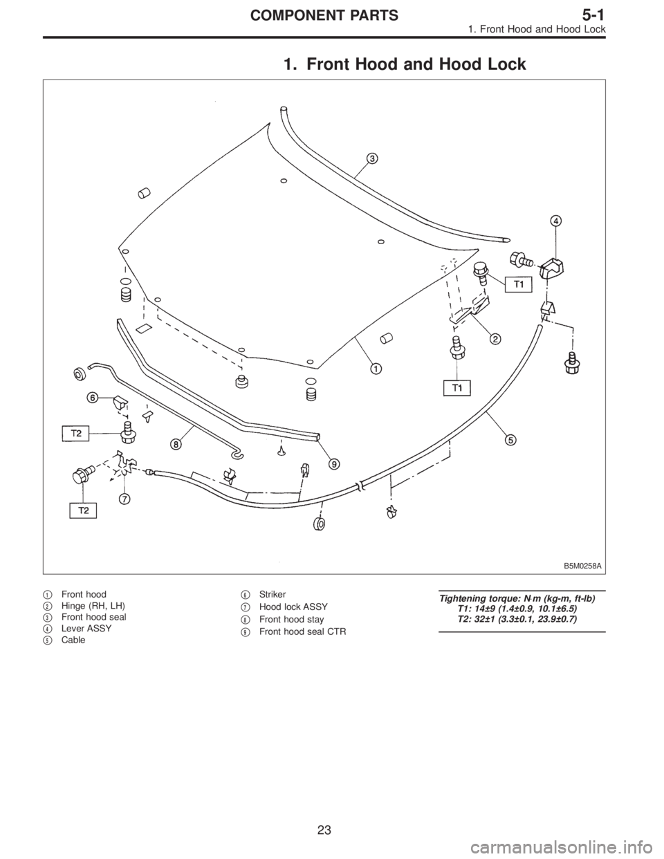
1. Front Hood and Hood Lock
B5M0258A
�1Front hood
�
2Hinge (RH, LH)
�
3Front hood seal
�
4Lever ASSY
�
5Cable�
6Striker
�
7Hood lock ASSY
�
8Front hood stay
�
9Front hood seal CTR
Tightening torque: N⋅m (kg-m, ft-lb)
T1: 14±9 (1.4±0.9, 10.1±6.5)
T2: 32±1 (3.3±0.1, 23.9±0.7)
23
5-1COMPONENT PARTS
1. Front Hood and Hood Lock
Page 1453 of 2890
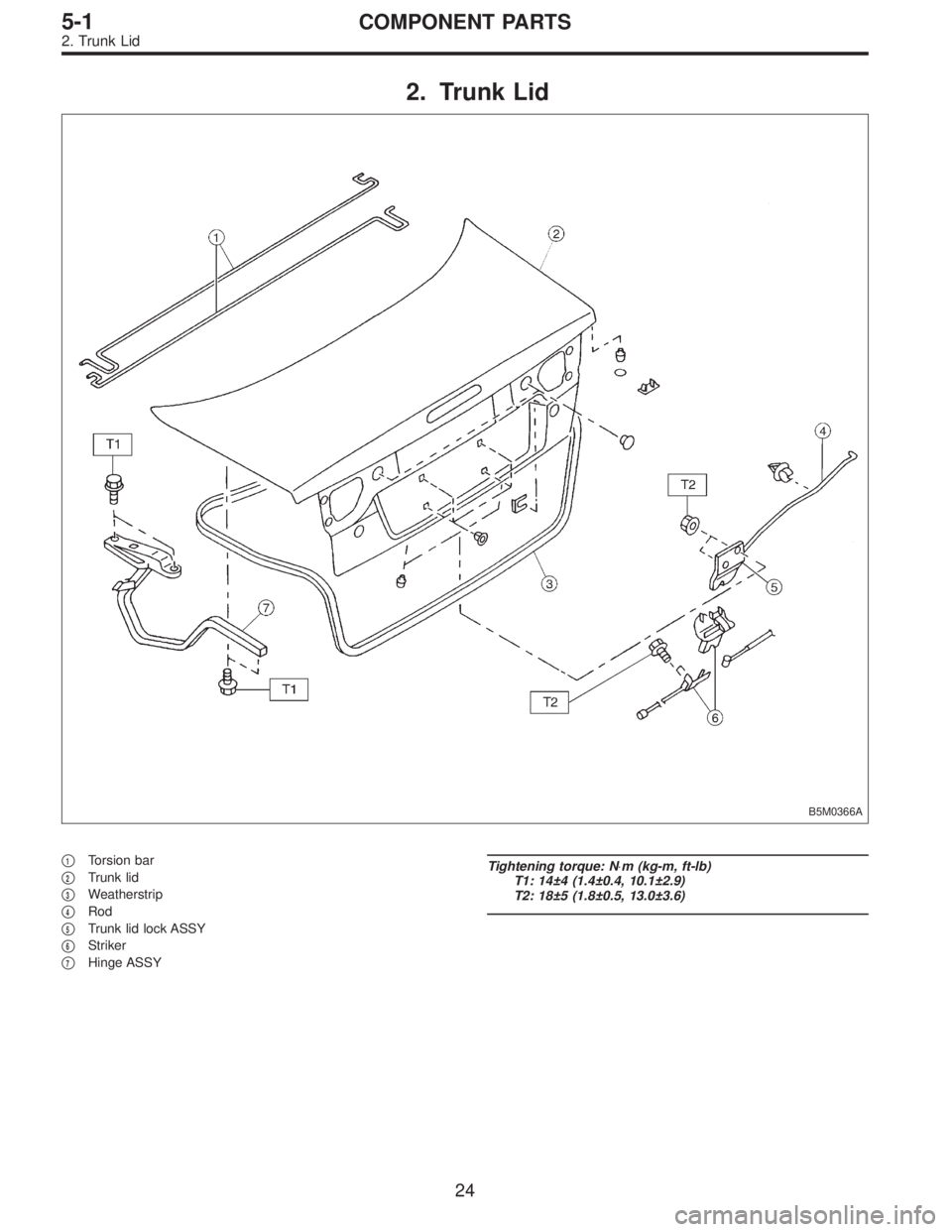
2. Trunk Lid
B5M0366A
�1Torsion bar
�
2Trunk lid
�
3Weatherstrip
�
4Rod
�
5Trunk lid lock ASSY
�
6Striker
�
7Hinge ASSY
Tightening torque: N⋅m (kg-m, ft-lb)
T1: 14±4 (1.4±0.4, 10.1±2.9)
T2: 18±5 (1.8±0.5, 13.0±3.6)
24
5-1COMPONENT PARTS
2. Trunk Lid
Page 1454 of 2890
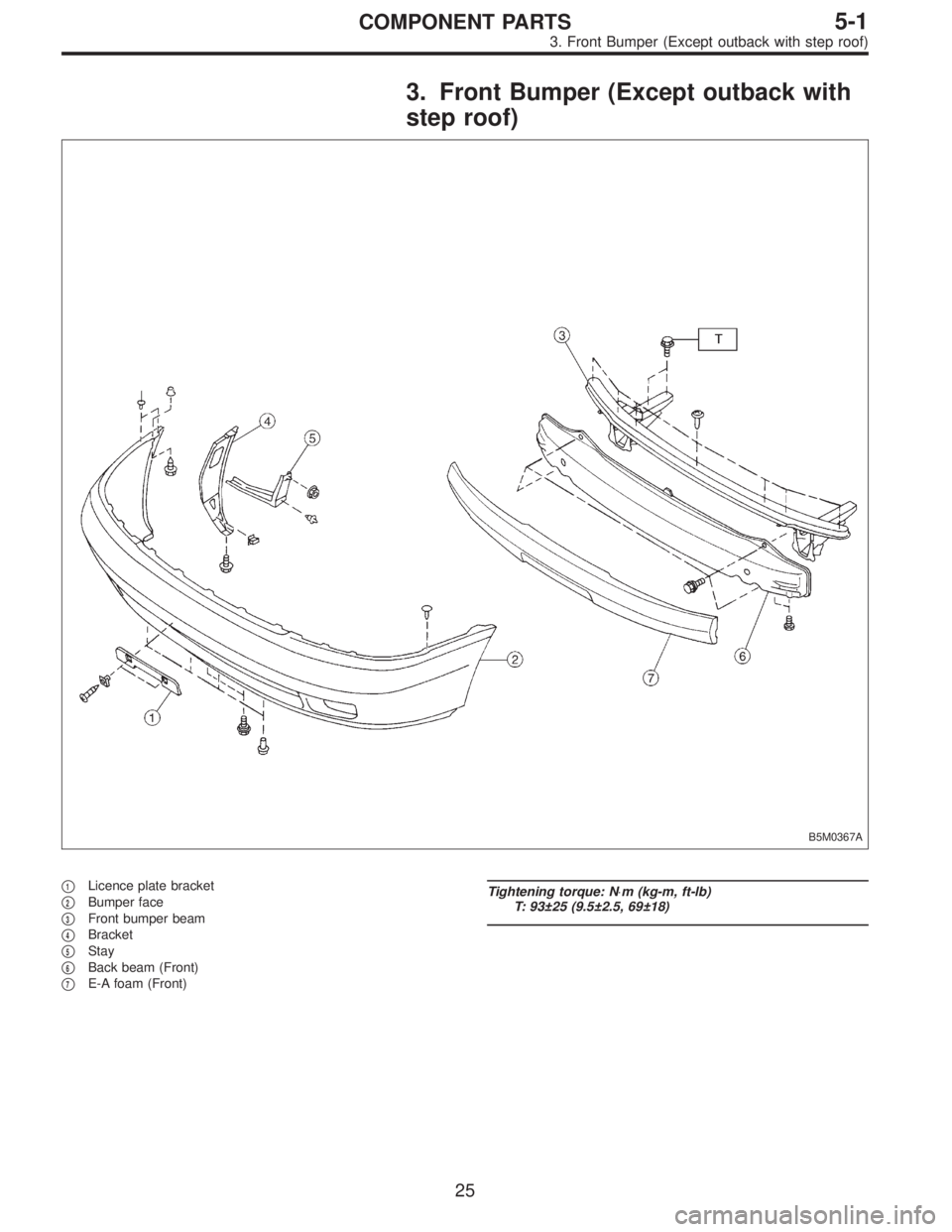
3. Front Bumper (Except outback with
step roof)
B5M0367A
�1Licence plate bracket
�
2Bumper face
�
3Front bumper beam
�
4Bracket
�
5Stay
�
6Back beam (Front)
�
7E-A foam (Front)
Tightening torque: N⋅m (kg-m, ft-lb)
T: 93±25 (9.5±2.5, 69±18)
25
5-1COMPONENT PARTS
3. Front Bumper (Except outback with step roof)
Page 1455 of 2890
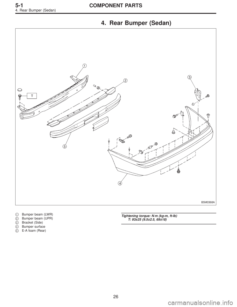
4. Rear Bumper (Sedan)
B5M0368A
�1Bumper beam (LWR)
�
2Bumper beam (UPR)
�
3Bracket (Side)
�
4Bumper surface
�
5E-A foam (Rear)
Tightening torque: N⋅m (kg-m, ft-lb)
T: 93±25 (9.5±2.5, 69±18)
26
5-1COMPONENT PARTS
4. Rear Bumper (Sedan)