Page 1287 of 2890
G4M0455
D: INSTALLATION
1) Install relay box cover on hydraulic unit.
2) Install hydraulic unit to bracket.
Tightening torque:
18±5 N⋅m (1.8±0.5 kg-m, 13.0±3.6 ft-lb)
3) Tighten bracket and motor ground lead as a unit.
Tightening torque:
32±10 N⋅m (3.3±1.0 kg-m, 24±7 ft-lb)
4) Connect brake pipes to their correct hydraulic unit con-
nections.
Tightening torque:
15
+3
�2N⋅m (1.5+0.3
�0.2kg-m, 10.8+2.2
�1.4ft-lb)
16. ABS Control Module (Except ABS
5.3 Type)
A: REMOVAL
1) Remove floor mat located under lower right side of front
seat.
G4M0468
2) Remove screw which secure ABS control module from
the body.
G4M0469
3) Disconnect connector from ABS control module.
80
4-4SERVICE PROCEDURE
15. Hydraulic Unit for ABS System (Except ABS 5.3 Type) - 16. ABS Control Module (Except ABS 5.3 Type)
Page 1288 of 2890
G4M0455
D: INSTALLATION
1) Install relay box cover on hydraulic unit.
2) Install hydraulic unit to bracket.
Tightening torque:
18±5 N⋅m (1.8±0.5 kg-m, 13.0±3.6 ft-lb)
3) Tighten bracket and motor ground lead as a unit.
Tightening torque:
32±10 N⋅m (3.3±1.0 kg-m, 24±7 ft-lb)
4) Connect brake pipes to their correct hydraulic unit con-
nections.
Tightening torque:
15
+3
�2N⋅m (1.5+0.3
�0.2kg-m, 10.8+2.2
�1.4ft-lb)
16. ABS Control Module (Except ABS
5.3 Type)
A: REMOVAL
1) Remove floor mat located under lower right side of front
seat.
G4M0468
2) Remove screw which secure ABS control module from
the body.
G4M0469
3) Disconnect connector from ABS control module.
80
4-4SERVICE PROCEDURE
15. Hydraulic Unit for ABS System (Except ABS 5.3 Type) - 16. ABS Control Module (Except ABS 5.3 Type)
Page 1289 of 2890
 Connect connector to ABS control module.
2) Install AB")
B: INSPECTION
Check that connector is connected correctly and that con-
nector terminal sliding resistance is correct.
G4M0469
C: INSTALLATION
1) Connect connector to ABS control module.
2) Install ABS control module on the body.
G4M0470
17. G Sensor for ABS System (Except
ABS 5.3 Type)
A: REMOVAL AND INSTALLATION
The G sensor is located on the right front wheel apron.
G4M0471
B: INSPECTION
1) Check to ensure that G sensor is securely installed on
front wheel apron, and that connector is properly installed.
2) Disconnect connector from G sensor and measure con-
tact resistance between terminals.
Condition of G sensor Standard
On flat surface 610±60Ω
* When slanting about
14°—21.3°(θ)610±60Ω,
More than 100 kΩ
NOTE:
�Tilt G sensor forward as shown in Figure. If it is tilted
backward, it will not operate.
�Hysteresis occurs during ON-OFF operation of sensor.
Sensor should turn OFF from ON (610Ω,More than 100
kΩ) when it is tilted in a range from 14°to 21.3°.
Tightening torque:
7.4±2.0 N⋅m (0.75±0.2 kg-m, 5.4±1.4 ft-lb)
81
4-4SERVICE PROCEDURE
16. ABS Control Module (Except ABS 5.3 Type)- 17. G Sensor for ABS System (Except ABS 5.3 Type)
Page 1290 of 2890
 Connect connector to ABS control module.
2) Install AB")
B: INSPECTION
Check that connector is connected correctly and that con-
nector terminal sliding resistance is correct.
G4M0469
C: INSTALLATION
1) Connect connector to ABS control module.
2) Install ABS control module on the body.
G4M0470
17. G Sensor for ABS System (Except
ABS 5.3 Type)
A: REMOVAL AND INSTALLATION
The G sensor is located on the right front wheel apron.
G4M0471
B: INSPECTION
1) Check to ensure that G sensor is securely installed on
front wheel apron, and that connector is properly installed.
2) Disconnect connector from G sensor and measure con-
tact resistance between terminals.
Condition of G sensor Standard
On flat surface 610±60Ω
* When slanting about
14°—21.3°(θ)610±60Ω,
More than 100 kΩ
NOTE:
�Tilt G sensor forward as shown in Figure. If it is tilted
backward, it will not operate.
�Hysteresis occurs during ON-OFF operation of sensor.
Sensor should turn OFF from ON (610Ω,More than 100
kΩ) when it is tilted in a range from 14°to 21.3°.
Tightening torque:
7.4±2.0 N⋅m (0.75±0.2 kg-m, 5.4±1.4 ft-lb)
81
4-4SERVICE PROCEDURE
16. ABS Control Module (Except ABS 5.3 Type)- 17. G Sensor for ABS System (Except ABS 5.3 Type)
Page 1291 of 2890

18. Brake Hose and Pipe
SUPPLEMENTAL RESTRAINT SYSTEM“AIRBAG”
Airbag system wiring harness is routed near the center
brake pipe.
CAUTION:
�All Airbag system wiring harness and connectors
are colored yellow. Do not use electrical test equip-
ment on these circuit.
�Be careful not to damage Airbag system wiring har-
ness when servicing the center brake pipe.
A: REMOVAL AND INSTALLATION
CAUTION:
�When removing and installing the brake pipe, make
sure that it is not bent.
�After installing the brake pipe and hose, bleed the
air.
�After installing the brake hose, make sure that it
does not touch the tire or suspension assembly, etc.
1. MODELS WITHOUT ABS
G4M0472
�1Union bolt
�
2Front brake hose RH
�
3Proportioning valve
�
4Front brake pipe
�
5Front adapter pipe (UPPER)
�
6Front adapter pipe (LOWER)
�
7Front brake hose LH�
8Center brake pipe ASSY
�
9Connector bracket
�
10Two-way connector
�
11Rear brake pipe RH
�
12Rear brake hose drum
�
13Rear brake pipe ASSY
�
14Rear brake pipe LH
Tightening torque: N⋅m (kg-m, ft-lb)
T1: 13±3 (1.3±0.3, 9.4±2.2)
T2: 15
+3
�2(1.5+0.3
�0.2, 10.8+2.2
�1.4)
T3: 18±3 (1.8±0.3, 13.0±2.2)
T4: 18±5 (1.8±0.5, 13.0±3.6)
82
4-4SERVICE PROCEDURE
18. Brake Hose and Pipe
Page 1292 of 2890
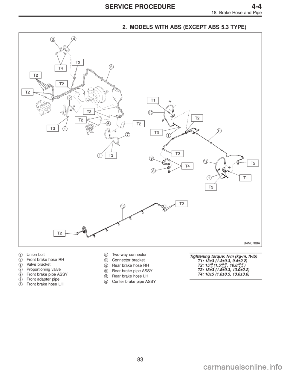
2. MODELS WITH ABS (EXCEPT ABS 5.3 TYPE)
B4M0708A
�1Union bolt
�
2Front brake hose RH
�
3Valve bracket
�
4Proportioning valve
�
5Front brake pipe ASSY
�
6Front adapter pipe
�
7Front brake hose LH�
8Two-way connector
�
9Connector bracket
�
10Rear brake hose RH
�
11Rear brake pipe ASSY
�
12Rear brake hose LH
�
13Center brake pipe ASSY
Tightening torque: N⋅m (kg-m, ft-lb)
T1: 13±3 (1.3±0.3, 9.4±2.2)
T2: 15
+3
�2(1.5+0.3
�0.2, 10.8+2.2
�1.4)
T3: 18±3 (1.8±0.3, 13.0±2.2)
T4: 18±5 (1.8±0.5, 13.0±3.6)
83
4-4SERVICE PROCEDURE
18. Brake Hose and Pipe
Page 1293 of 2890
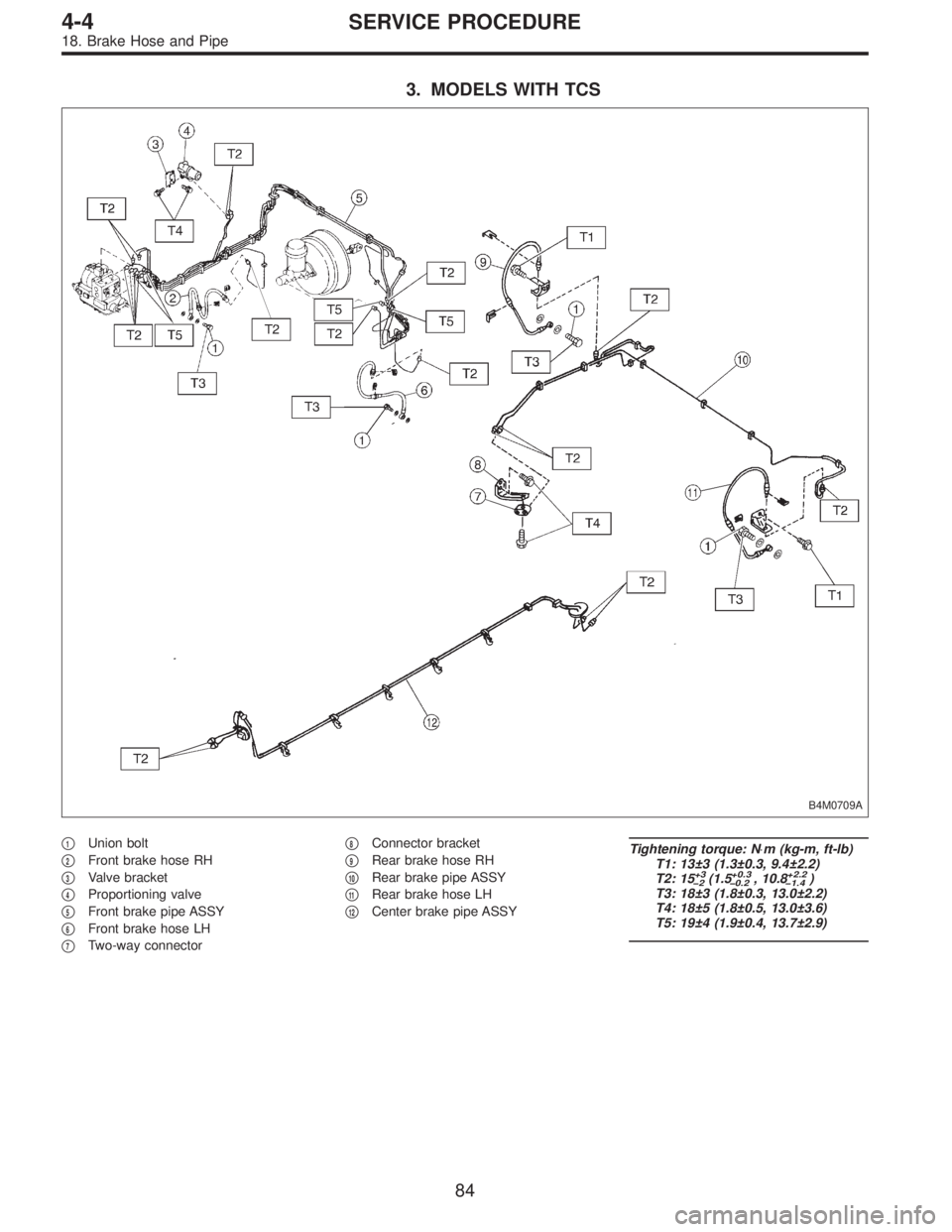
3. MODELS WITH TCS
B4M0709A
�1Union bolt
�
2Front brake hose RH
�
3Valve bracket
�
4Proportioning valve
�
5Front brake pipe ASSY
�
6Front brake hose LH
�
7Two-way connector�
8Connector bracket
�
9Rear brake hose RH
�
10Rear brake pipe ASSY
�
11Rear brake hose LH
�
12Center brake pipe ASSY
Tightening torque: N⋅m (kg-m, ft-lb)
T1: 13±3 (1.3±0.3, 9.4±2.2)
T2: 15
+3
�2(1.5+0.3
�0.2, 10.8+2.2
�1.4)
T3: 18±3 (1.8±0.3, 13.0±2.2)
T4: 18±5 (1.8±0.5, 13.0±3.6)
T5: 19±4 (1.9±0.4, 13.7±2.9)
84
4-4SERVICE PROCEDURE
18. Brake Hose and Pipe
Page 1294 of 2890
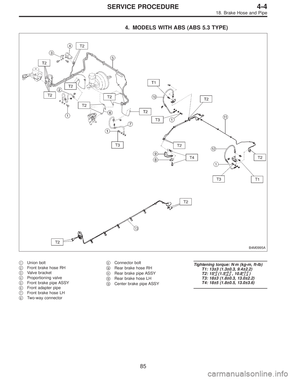
4. MODELS WITH ABS (ABS 5.3 TYPE)
B4M0995A
�1Union bolt
�
2Front brake hose RH
�
3Valve bracket
�
4Proportioning valve
�
5Front brake pipe ASSY
�
6Front adapter pipe
�
7Front brake hose LH
�
8Two-way connector�
9Connector bolt
�
10Rear brake hose RH
�
11Rear brake pipe ASSY
�
12Rear brake hose LH
�
13Center brake pipe ASSY
Tightening torque: N⋅m (kg-m, ft-lb)
T1: 13±3 (1.3±0.3, 9.4±2.2)
T2: 15
+3
�2(1.5+0.3
�0.2, 10.8+2.2
�1.4)
T3: 18±3 (1.8±0.3, 13.0±2.2)
T4: 18±5 (1.8±0.5, 13.0±3.6)
85
4-4SERVICE PROCEDURE
18. Brake Hose and Pipe
 Install relay box cover on hydraulic unit.
2) Install hydraulic unit to bracket.
Tightening torque:
18±5 N⋅m (1.8±0.5 kg-m, 13.0±3.6 ft-lb)
3) Tighten bracket and motor")
 Install relay box cover on hydraulic unit.
2) Install hydraulic unit to bracket.
Tightening torque:
18±5 N⋅m (1.8±0.5 kg-m, 13.0±3.6 ft-lb)
3) Tighten bracket and motor")