Page 1229 of 2890
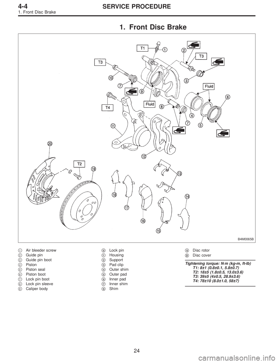
1. Front Disc Brake
B4M0065B
�1Air bleeder screw
�
2Guide pin
�
3Guide pin boot
�
4Piston
�
5Piston seal
�
6Piston boot
�
7Lock pin boot
�
8Lock pin sleeve
�
9Caliper body�
10Lock pin
�
11Housing
�
12Support
�
13Pad clip
�
14Outer shim
�
15Outer pad
�
16Inner pad
�
17Inner shim
�
18Shim�
19Disc rotor
�
20Disc cover
Tightening torque: N⋅m (kg-m, ft-lb)
T1: 8±1 (0.8±0.1, 5.8±0.7)
T2: 18±5 (1.8±0.5, 13.0±3.6)
T3: 39±5 (4±0.5, 28.9±3.6)
T4: 78±10 (8.0±1.0, 58±7)
24
4-4SERVICE PROCEDURE
1. Front Disc Brake
Page 1236 of 2890
 Install disc rotor on hub.
2) Install support on housing.
Tightening torque:
78±10 N⋅m (8±1 kg-m, 58±7 ft-lb)
CAUTION:
�Always replace the pads for both the left and ri")
G4M0363
F: INSTALLATION
1) Install disc rotor on hub.
2) Install support on housing.
Tightening torque:
78±10 N⋅m (8±1 kg-m, 58±7 ft-lb)
CAUTION:
�Always replace the pads for both the left and right
wheels at the same time. Also replace pad clips if they
are twisted or worn.
�A wear indicator is provided on the inner disc brake
pad. If the pad wears down to such an extent that the
end of the wear indicator contacts the disc rotor, a
squeaking sound is produced as the wheel rotates. If
this sound is heard, replace the pad.
�When replacing the pad, replace pads of the right
and left wheels at the same time.
3) Apply thin coat of PBC GREASE (Part No. 003607000)
to the frictional portion between pad and pad clip.
4) Install pads, rubber coated shim and stainless shim on
support.
5) Install caliper body on support.
Tightening torque:
39±5 N⋅m (4±0.5 kg-m, 28.9±3.6 ft-lb)
6) Connect brake hose.
Tightening torque:
18±3 N⋅m (1.8±0.3 kg-m, 13.0±2.2 ft-lb)
CAUTION:
Replace brake hose gaskets with new ones.
7) Bleed air from brake system.
31
4-4SERVICE PROCEDURE
1. Front Disc Brake
Page 1237 of 2890
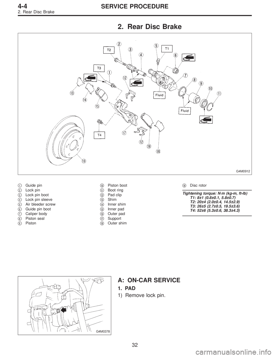
2. Rear Disc Brake
G4M0912
�1Guide pin
�
2Lock pin
�
3Lock pin boot
�
4Lock pin sleeve
�
5Air bleeder screw
�
6Guide pin boot
�
7Caliper body
�
8Piston seal
�
9Piston�
10Piston boot
�
11Boot ring
�
12Pad clip
�
13Shim
�
14Inner shim
�
15Inner pad
�
16Outer pad
�
17Support
�
18Outer shim�
19Disc rotor
Tightening torque: N⋅m (kg-m, ft-lb)
T1: 8±1 (0.8±0.1, 5.8±0.7)
T2: 20±4 (2.0±0.4, 14.5±2.9)
T3: 26±5 (2.7±0.5, 19.5±3.6)
T4: 52±6 (5.3±0.6, 38.3±4.3)
G4M0378
A: ON-CAR SERVICE
1. PAD
1) Remove lock pin.
32
4-4SERVICE PROCEDURE
2. Rear Disc Brake
Page 1238 of 2890
 Raise caliper body.
3) Remove pad from support.
G4M0362
4) Check pad thickness (including back metal).
Pad thickness: A
Standard value 15.0 mm (0.591 in)
Wear limit 6.5 mm (0.256 in)
CAUTIO")
G4M0379
2) Raise caliper body.
3) Remove pad from support.
G4M0362
4) Check pad thickness (including back metal).
Pad thickness: A
Standard value 15.0 mm (0.591 in)
Wear limit 6.5 mm (0.256 in)
CAUTION:
�Always replace the pads for both the left and right
wheels at the same time. Also replace pad clips if they
are twisted or worn.
�A wear indicator is provided on the inner disc brake
pad. If the pad wears down to such an extent that the
end of the wear indicator contacts the disc rotor, a
squeaking sound is produced as the wheel rotates. If
this sound is heard, replace the pad.
�Replace pad if there is oil or grease on it.
G4M0363
5) Apply thin coat of PBC GREASE (Part No. 03607000)
to the frictional portion between pad and pad clip.
6) Install pad on support.
7) Install caliper body on support.
Tightening torque:
20±4 N⋅m (2.0±0.4 kg-m, 14.5±2.9 ft-lb)
NOTE:
If it is difficult to push piston during pad replacement,
loosen air bleeder to facilitate work.
33
4-4SERVICE PROCEDURE
2. Rear Disc Brake
Page 1242 of 2890
 Install disc rotor on hub.
2) Install support on back plate.
Tightening torque:
52±6 N⋅m (5.3±0.6 kg-m, 38.3±4.3 ft-lb)
CAUTION:
�Always replace the pads for both the left and")
F: INSTALLATION
1) Install disc rotor on hub.
2) Install support on back plate.
Tightening torque:
52±6 N⋅m (5.3±0.6 kg-m, 38.3±4.3 ft-lb)
CAUTION:
�Always replace the pads for both the left and right
wheels at the same time. Also replace pad clips if they
are twisted or worn.
�A wear indicator is provided on the inner disc brake
pad. If the pad wears down to such an extent that the
end of the wear indicator contacts the disc rotor, a
squeaking sound is produced as the wheel rotates. If
this sound is heard, replace the pad.
�Replace pads if there is oil or grease on them.
3) Apply thin coat of PBC GREASE (Part No. 003607000)
to the frictional portion between pad and pad clip.
G4M0363
4) Install pads on support.
5) Install caliper body on support.
Tightening torque:
20±4 N⋅m (2.0±0.4 kg-m, 14.5±2.9 ft-lb)
6) Connect brake hose.
Tightening torque:
18±3 N⋅m (1.8±0.3 kg-m, 13.0±2.2 ft-lb)
CAUTION:
�The brake hose must be connected without any
twist.
�Replace brake hose gaskets with new ones.
7) Bleed air from brake system.
37
4-4SERVICE PROCEDURE
2. Rear Disc Brake
Page 1243 of 2890
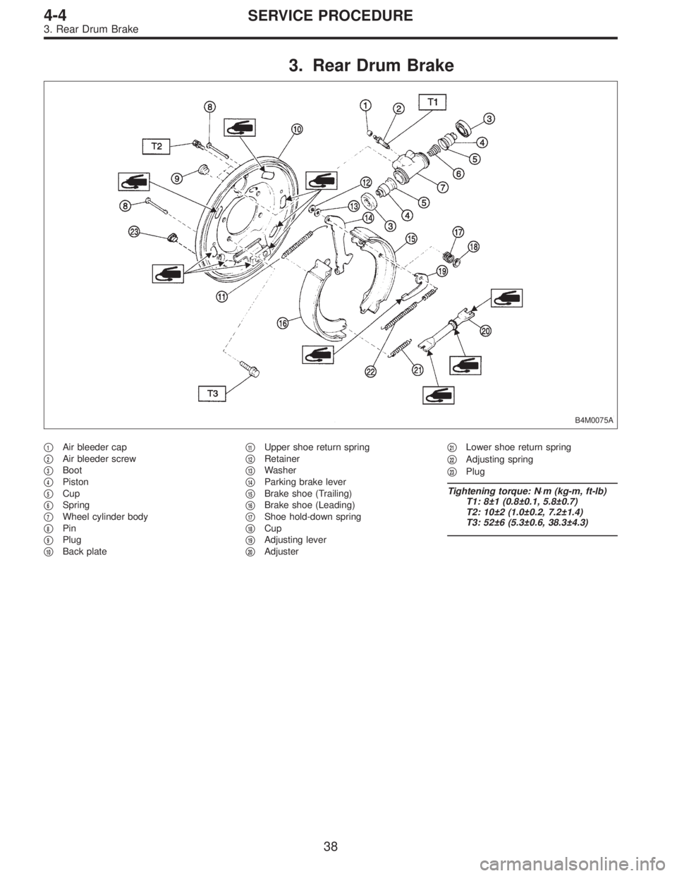
3. Rear Drum Brake
B4M0075A
�1Air bleeder cap
�
2Air bleeder screw
�
3Boot
�
4Piston
�
5Cup
�
6Spring
�
7Wheel cylinder body
�
8Pin
�
9Plug
�
10Back plate�
11Upper shoe return spring
�
12Retainer
�
13Washer
�
14Parking brake lever
�
15Brake shoe (Trailing)
�
16Brake shoe (Leading)
�
17Shoe hold-down spring
�
18Cup
�
19Adjusting lever
�
20Adjuster�
21Lower shoe return spring
�
22Adjusting spring
�
23Plug
Tightening torque: N⋅m (kg-m, ft-lb)
T1: 8±1 (0.8±0.1, 5.8±0.7)
T2: 10±2 (1.0±0.2, 7.2±1.4)
T3: 52±6 (5.3±0.6, 38.3±4.3)
38
4-4SERVICE PROCEDURE
3. Rear Drum Brake
Page 1247 of 2890
 Assembly i")
D: ASSEMBLY
1. WHEEL CYLINDER
Clean all parts in brake fluid. Check and replace faulty
parts.
�Cup and boot for damage or fatigue
�Cylinder, piston and spring or damage or rust formation
1) Assembly is the reverse order of disassembly.
G4M0404
(1) When installing the cup, use ST, apply brake fluid
to the frictional surface for smooth installation and pay
attention to cup direction.
(2) STs are available in different sizes.
CAUTION:
�When replacing the repair kit, make sure that the
sizes of cylinder and cup are the same as those which
were replaced.
�Use only the tool of the correct size.
ST: ADAPTER
Applicable size Part No.
17.46 mm (11/16 in) 925460000
19.05 mm (3/4 in) 926460000
CAUTION:
While assembling, be careful to prevent any metal
chip, dust or dirt from entering the wheel cylinder.
G4M0405
2) Apply rubber grease to the boot inside as shown in
Figure.
Grease:
NIGLUBE RX-2 (Part No. 003606000)
CAUTION:
Never use brake grease.
G4M0401
E: INSTALLATION
1. WHEEL CYLINDER
Install wheel cylinder on back plate, and tighten bolts.
Tightening torque:
10±2 N⋅m (1.0±0.2 kg-m, 7.2±1.4 ft-lb)
42
4-4SERVICE PROCEDURE
3. Rear Drum Brake
Page 1248 of 2890
 Clean back plate and wheel cylinder.
2) Apply grease to portions indicated by arrows in Figure.
Brake grease:
Dow Corning Molykote No. 7439 (Part No.
725191460)
G4M04")
G4M0407
2. BRAKE DRUM AND SHOE
1) Clean back plate and wheel cylinder.
2) Apply grease to portions indicated by arrows in Figure.
Brake grease:
Dow Corning Molykote No. 7439 (Part No.
725191460)
G4M0408
3) Apply grease to adjusting screw and both ends of
adjuster.
Brake grease:
Dow Corning Molykote No. 7439 (Part No.
725191460)
4) Connect upper shoe return spring to shoes.
G4M0409
5) While positioning shoes (one at a time) in groove on
wheel cylinder, secure shoes.
6) Connect lower shoe return spring.
7) Fix shoes by connecting hold-down cup to hold-down
pin.
G4M0400
3. BRAKE ASSEMBLY
1) Install brake assembly on housing, and tighten bolts to
install back plate.
Tightening torque:
52±6 N⋅m (5.3±0.6 kg-m, 38.3±4.3 ft-lb)
2) Install hub.
3) Connect brake pipe, and tighten brake pipe flange nut.
Tightening torque:
15
+3
�2N⋅m (1.5+0.3
�0.2kg-m, 10.8+2.2
�1.4ft-lb)
4) Set the outside diameter of brake shoes less than 0.5
to 0.8 mm (0.020 to 0.031 in) in comparison with the inside
diameter of brake drum.
5) Install brake drum.
6) After installing brake assembly, bleed air from brake
line.
43
4-4SERVICE PROCEDURE
3. Rear Drum Brake