Page 1144 of 2890

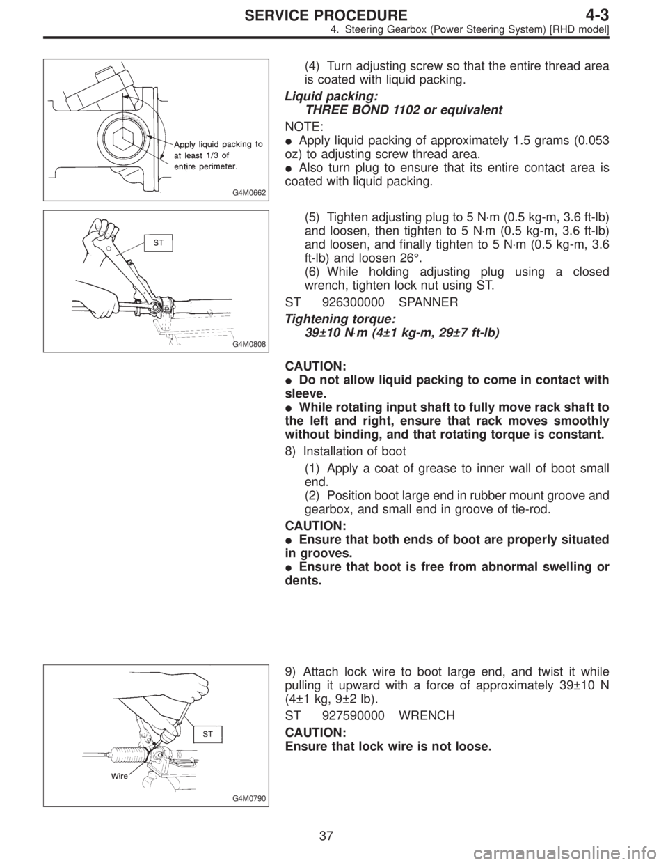
G4M0662
(4) Turn adjusting screw so that the entire thread area
is coated with liquid packing.
Liquid packing:
THREE BOND 1102 or equivalent
NOTE:
�Apply liquid packing of approximately 1.5 grams (0.053
oz) to adjusting screw thread area.
�Also turn plug to ensure that its entire contact area is
coated with liquid packing.
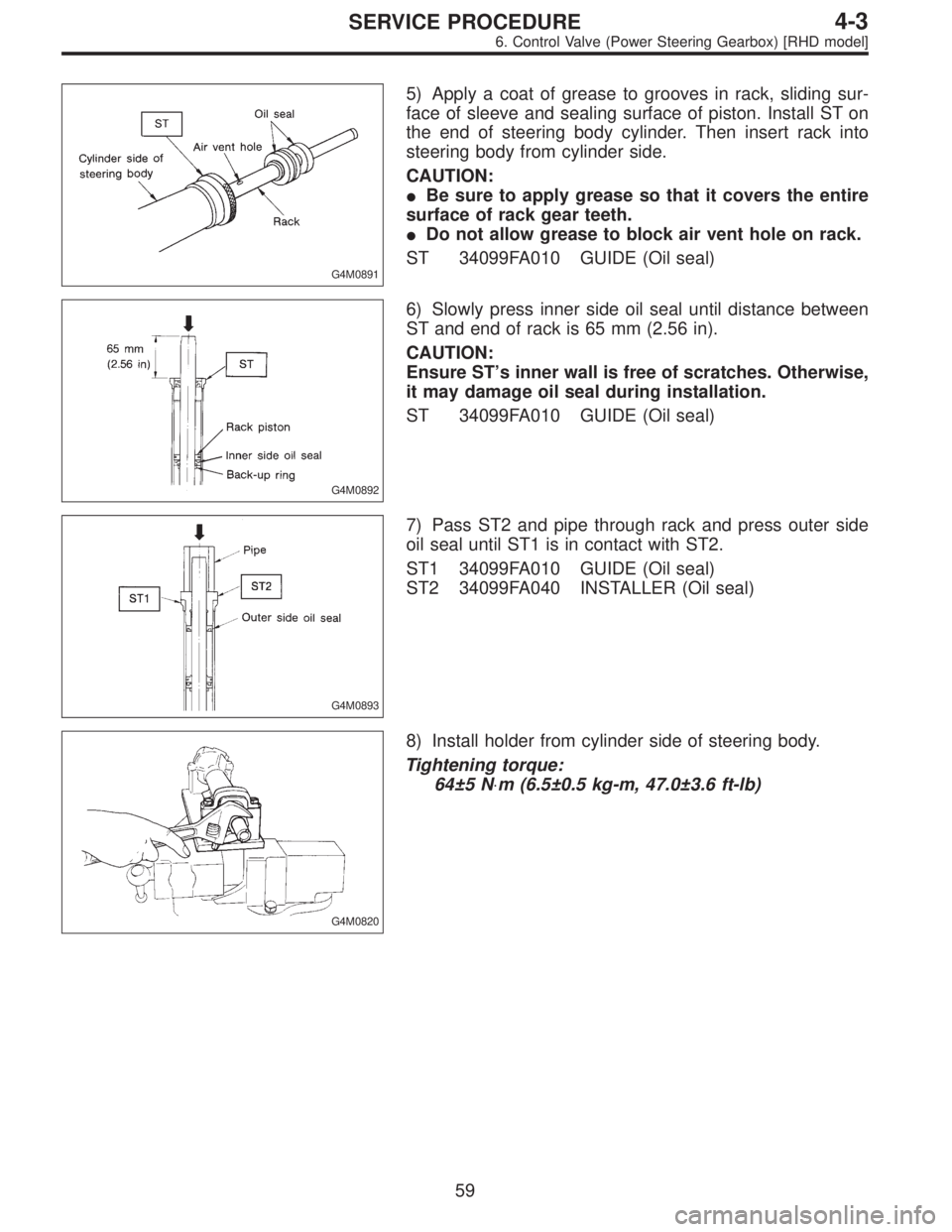
G4M0808
(5) Tighten adjusting plug to 5 N⋅m (0.5 kg-m, 3.6 ft-lb)
and loosen, then tighten to 5 N⋅m (0.5 kg-m, 3.6 ft-lb)
and loosen, and finally tighten to 5 N⋅m (0.5 kg-m, 3.6
ft-lb) and loosen 26°.
(6) While holding adjusting plug using a closed
wrench, tighten lock nut using ST.
ST 926300000 SPANNER
Tightening torque:
39±10 N⋅m (4±1 kg-m, 29±7 ft-lb)
CAUTION:
�Do not allow liquid packing to come in contact with
sleeve.
�While rotating input shaft to fully move rack shaft to
the left and right, ensure that rack moves smoothly
without binding, and that rotating torque is constant.
8) Installation of boot
(1) Apply a coat of grease to inner wall of boot small
end.
(2) Position boot large end in rubber mount groove and
gearbox, and small end in groove of tie-rod.
CAUTION:
�Ensure that both ends of boot are properly situated
in grooves.
�Ensure that boot is free from abnormal swelling or
dents.
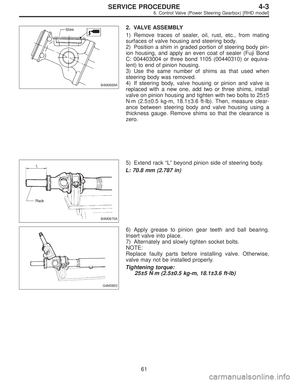
G4M0790
9) Attach lock wire to boot large end, and twist it while
pulling it upward with a force of approximately 39±10 N
(4±1 kg, 9±2 lb).
ST 927590000 WRENCH
CAUTION:
Ensure that lock wire is not loose.
37
4-3SERVICE PROCEDURE
4. Steering Gearbox (Power Steering System) [RHD model]
Page 1145 of 2890
G4M0810
10) Then bend wire end along boot as shown.
G4M0812
11) Install clip using pliers.
CAUTION:
After installing clip, ensure that boot’s small end is
properly positioned in groove on tie-rod.
12) Install pipes A and B.
Tightening torque:
20±4 N⋅m (2.0±0.4 kg-m, 14.5±2.9 ft-lb)
G4M0132
E: INSTALLATION
Installation is in the reverse order of removal.
Do the following:
CAUTION:
When adjusting toe-in, hold boot as shown to prevent
it from being rotated or twisted. If twisted, straighten it.
G4M0133
F: ADJUSTMENT
1) Adjust front toe.
Standard of front toe:
IN 3—OUT 3 mm (IN 0.12—OUT 0.12 in)
38
4-3SERVICE PROCEDURE
4. Steering Gearbox (Power Steering System) [RHD model]
Page 1155 of 2890
G4M0158
2. VALVE ASSEMBLY
1) Apply genuine grease to pinion gear and bearing of
valve assembly.
B4M0135
2) Install packing on valve assembly. Insert valve assem-
bly into place while facing rack teeth toward pinion.
CAUTION:
Be sure to use a new packing.
NOTE:
Do not allow packing to be caught when installing valve
assembly.
3) Tighten bolts alternately to secure valve assembly.
Tightening torque:
25±5 N⋅m (2.5±0.5 kg-m, 18.1±3.6 ft-lb)
CAUTION:
Be sure to alternately tighten bolts.
48
4-3SERVICE PROCEDURE
5. Control Valve (Power Steering Gearbox) [LHD model]
Page 1166 of 2890

G4M0891
5) Apply a coat of grease to grooves in rack, sliding sur-
face of sleeve and sealing surface of piston. Install ST on
the end of steering body cylinder. Then insert rack into
steering body from cylinder side.
CAUTION:
�Be sure to apply grease so that it covers the entire
surface of rack gear teeth.
�Do not allow grease to block air vent hole on rack.
ST 34099FA010 GUIDE (Oil seal)
G4M0892
6) Slowly press inner side oil seal until distance between
ST and end of rack is 65 mm (2.56 in).
CAUTION:
Ensure ST’s inner wall is free of scratches. Otherwise,
it may damage oil seal during installation.
ST 34099FA010 GUIDE (Oil seal)
G4M0893
7) Pass ST2 and pipe through rack and press outer side
oil seal until ST1 is in contact with ST2.
ST1 34099FA010 GUIDE (Oil seal)
ST2 34099FA040 INSTALLER (Oil seal)
G4M0820
8) Install holder from cylinder side of steering body.
Tightening torque:
64±5 N⋅m (6.5±0.5 kg-m, 47.0±3.6 ft-lb)
59
4-3SERVICE PROCEDURE
6. Control Valve (Power Steering Gearbox) [RHD model]
Page 1168 of 2890

B4M0669A
2. VALVE ASSEMBLY
1) Remove traces of sealer, oil, rust, etc., from mating
surfaces of valve housing and steering body.
2) Position a shim in graded portion of steering body pin-
ion housing, and apply an even coat of sealer (Fuji Bond
C: 004403004 or three bond 1105 (00440310) or equiva-
lent) to end of pinion housing.
3) Use the same number of shims as that used when
steering body was removed.
4) If steering body, valve housing or pinion and valve is
replaced with a new one, add two or three shims, install
valve on pinion housing and tighten with two bolts to 25±5
N⋅m (2.5±0.5 kg-m, 18.1±3.6 ft-lb). Then, measure clear-
ance between steering body and valve housing using a
thickness gauge. Remove shims so that the clearance is
zero.
B4M0670A
5) Extend rack“L”beyond pinion side of steering body.
L: 70.8 mm (2.787 in)
G4M0853
6) Apply grease to pinion gear teeth and ball bearing.
Insert valve into place.
7) Alternately and slowly tighten socket bolts.
NOTE:
Replace faulty parts before installing valve. Otherwise,
valve may not be installed properly.
Tightening torque:
25±5 N⋅m (2.5±0.5 kg-m, 18.1±3.6 ft-lb)
61
4-3SERVICE PROCEDURE
6. Control Valve (Power Steering Gearbox) [RHD model]
Page 1171 of 2890
B4M0556A
C: ASSEMBLY
1) Interconnect pipes C and D.
Tightening torque:
Joint nut
15±5 N⋅m (1.5±0.5 kg-m, 10.8±3.6 ft-lb)
CAUTION:
Visually check that hose between tank and pipe D is
free from bending or twisting.
2) Tighten bolt A.
Tightening torque:
13±3 N⋅m (1.3±0.3 kg-m, 9.4±2.2 ft-lb)
G4M0165
3) Temporarily connect pipes C and D to pipes (on the
gearbox side).
64
4-3SERVICE PROCEDURE
7. Pipe Assembly (Power Steering System) [LHD model]
Page 1172 of 2890
B4M0557A
4) Temporarily install clamp E on pipes C and D.
CAUTION:
Ensure that the letter“8”on each clamp side are
diagonally opposite each other as shown in the figure.
5) Tighten clamp E firmly.
Tightening torque:
7.4±2.0 N⋅m (0.75±0.20 kg-m, 5.4±1.4 ft-lb)
6) Tighten joint nut.
Tightening torque:
15±5 N⋅m (1.5±0.5 kg-m, 10.8±3.6 ft-lb)
G4M0099
7) Connect pipes A and B to four pipe joints of gearbox.
Connect upper pipe B first, and lower pipe A second.
Tightening torque:
13±3 N⋅m (1.3±0.3 kg-m, 9.4±2.2 ft-lb)
8) Install jack-up plate.
9) Connect battery minus terminal.
10) Feed the specified fluid and discharge air.
NOTE:
Never start the engine before feeding the fluid; otherwise
vane pump might be seized up.
65
4-3SERVICE PROCEDURE
7. Pipe Assembly (Power Steering System) [LHD model]
Page 1176 of 2890
B4M0556A
C: ASSEMBLY
1) Interconnect pipes C and D.
Tightening torque:
Joint nut
15±5 N⋅m (1.5±0.5 kg-m, 10.8±3.6 ft-lb)
CAUTION:
Visually check that hose between tank and pipe D is
free from bending or twisting.
2) Tighten bolt A.
Tightening torque:
13±3 N⋅m (1.3±0.3 kg-m, 9.4±2.2 ft-lb)
B4M0673A
3) Temporarily connect pipes C and D to control valve of
gearbox.
B4M0667A
4) Temporarily install clamp E on pipes C and D.
CAUTION:
Ensure that the letter“8”side of clamp E is on the pipe
C side as shown in the figure.
5) Tighten clamp E firmly.
Tightening torque:
7.4±2.0 N⋅m (0.75±0.20 kg-m, 5.4±1.4 ft-lb)
6) Tighten joint nut.
Tightening torque:
15±5 N⋅m (1.5±0.5 kg-m, 10.8±3.6 ft-lb)
69
4-3SERVICE PROCEDURE
8. Pipe Assembly (Power Steering System) [RHD model]