Page 1203 of 2890

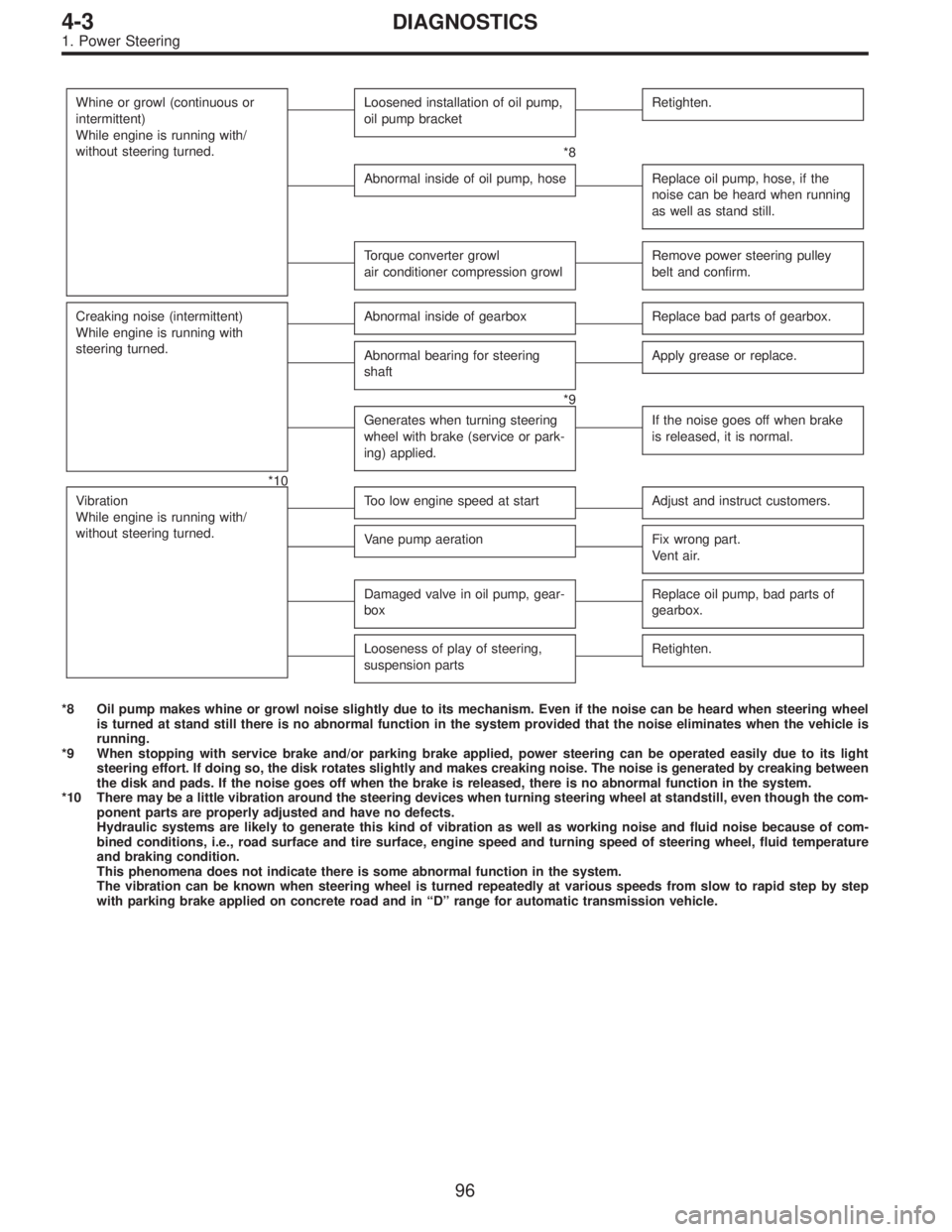
Whine or growl (continuous or
intermittent)
While engine is running with/
without steering turned.Loosened installation of oil pump,
oil pump bracketRetighten.
*8
Abnormal inside of oil pump, hoseReplace oil pump, hose, if the
noise can be heard when running
as well as stand still.
Torque converter growl
air conditioner compression growlRemove power steering pulley
belt and confirm.
Creaking noise (intermittent)
While engine is running with
steering turned.Abnormal inside of gearboxReplace bad parts of gearbox.
Abnormal bearing for steering
shaftApply grease or replace.
*9
Generates when turning steering
wheel with brake (service or park-
ing) applied.If the noise goes off when brake
is released, it is normal.
*10
Vibration
While engine is running with/
without steering turned.
Too low engine speed at startAdjust and instruct customers.
Vane pump aerationFix wrong part.
Vent air.
Damaged valve in oil pump, gear-
boxReplace oil pump, bad parts of
gearbox.
Looseness of play of steering,
suspension partsRetighten.
*8 Oil pump makes whine or growl noise slightly due to its mechanism. Even if the noise can be heard when steering wheel
is turned at stand still there is no abnormal function in the system provided that the noise eliminates when the vehicle is
running.
*9 When stopping with service brake and/or parking brake applied, power steering can be operated easily due to its light
steering effort. If doing so, the disk rotates slightly and makes creaking noise. The noise is generated by creaking between
the disk and pads. If the noise goes off when the brake is released, there is no abnormal function in the system.
*10 There may be a little vibration around the steering devices when turning steering wheel at standstill, even though the com-
ponent parts are properly adjusted and have no defects.
Hydraulic systems are likely to generate this kind of vibration as well as working noise and fluid noise because of com-
bined conditions, i.e., road surface and tire surface, engine speed and turning speed of steering wheel, fluid temperature
and braking condition.
This phenomena does not indicate there is some abnormal function in the system.
The vibration can be known when steering wheel is turned repeatedly at various speeds from slow to rapid step by step
with parking brake applied on concrete road and in“D”range for automatic transmission vehicle.
96
4-3DIAGNOSTICS
1. Power Steering
Page 1206 of 2890

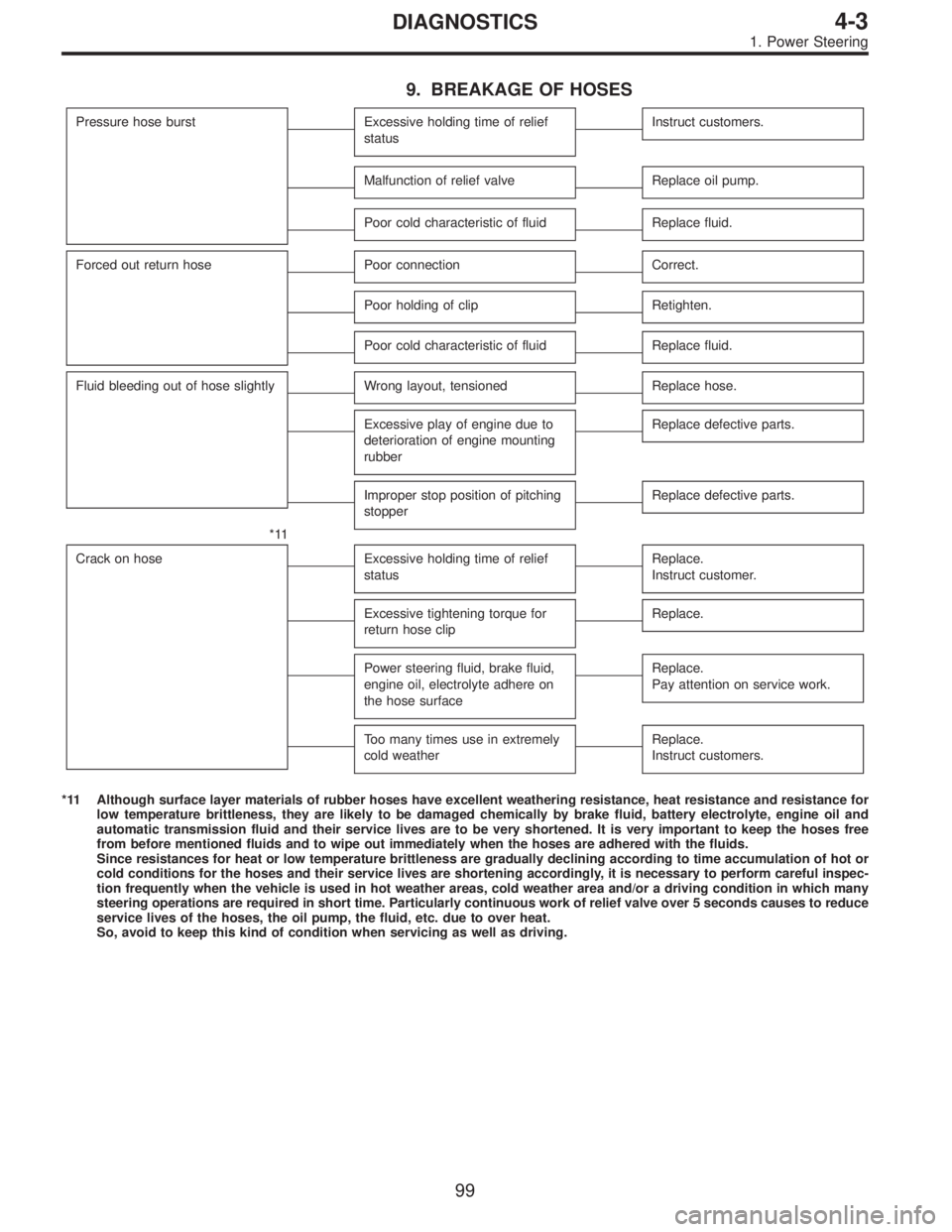
9. BREAKAGE OF HOSES
Pressure hose burstExcessive holding time of relief
statusInstruct customers.
Malfunction of relief valveReplace oil pump.
Poor cold characteristic of fluidReplace fluid.
Forced out return hosePoor connectionCorrect.
Poor holding of clipRetighten.
Poor cold characteristic of fluidReplace fluid.
Fluid bleeding out of hose slightlyWrong layout, tensionedReplace hose.
Excessive play of engine due to
deterioration of engine mounting
rubberReplace defective parts.
Improper stop position of pitching
stopperReplace defective parts.
*11
Crack on hose
Excessive holding time of relief
statusReplace.
Instruct customer.
Excessive tightening torque for
return hose clipReplace.
Power steering fluid, brake fluid,
engine oil, electrolyte adhere on
the hose surfaceReplace.
Pay attention on service work.
Too many times use in extremely
cold weatherReplace.
Instruct customers.
*11 Although surface layer materials of rubber hoses have excellent weathering resistance, heat resistance and resistance for
low temperature brittleness, they are likely to be damaged chemically by brake fluid, battery electrolyte, engine oil and
automatic transmission fluid and their service lives are to be very shortened. It is very important to keep the hoses free
from before mentioned fluids and to wipe out immediately when the hoses are adhered with the fluids.
Since resistances for heat or low temperature brittleness are gradually declining according to time accumulation of hot or
cold conditions for the hoses and their service lives are shortening accordingly, it is necessary to perform careful inspec-
tion frequently when the vehicle is used in hot weather areas, cold weather area and/or a driving condition in which many
steering operations are required in short time. Particularly continuous work of relief valve over 5 seconds causes to reduce
service lives of the hoses, the oil pump, the fluid, etc. due to over heat.
So, avoid to keep this kind of condition when servicing as well as driving.
99
4-3DIAGNOSTICS
1. Power Steering
Page 1214 of 2890
1. Front Disc Brake
1. EXCEPT 2500 cc AND OUTBACK (STEP ROOF)
MODEL
B4M0065A
�1Air bleeder screw
�
2Guide pin
�
3Guide pin boot
�
4Piston
�
5Piston seal
�
6Piston boot
�
7Lock pin boot
�
8Lock pin sleeve
�
9Caliper body�
10Lock pin
�
11Housing
�
12Support
�
13Pad clip
�
14Outer shim
�
15Outer pad
�
16Inner pad
�
17Inner shim
�
18Shim�
19Disc rotor
�
20Disc cover
Tightening torque: N⋅m (kg-m, ft-lb)
T1: 8±1 (0.8±0.1, 5.8±0.7)
T2: 18±5 (1.8±0.5, 13.0±3.6)
T3: 39±5 (4±0.5, 28.9±3.6)
T4: 78±10 (8.0±1.0, 58±7)
9
4-4COMPONENT PARTS
1. Front Disc Brake
Page 1215 of 2890
2. 2500 cc AND OUTBACK (STEP ROOF) MODEL
G4M0990
�1Lock pin
�
2Lock pin sleeve
�
3Lock pin boot
�
4Caliper body
�
5Air bleeder screw
�
6Guide pin
�
7Guide pin boot
�
8Piston seal
�
9Piston�
10Piston boot
�
11Boot ring
�
12Support
�
13Pad clip
�
14Outer shim
�
15Pad (Outside)
�
16Pad (Inside)
�
17Inner shim
�
18Shim�
19Disc rotor
�
20Disc cover
Tightening torque: N⋅m (kg-m, ft-lb)
T1: 8±1 (0.8±0.1, 5.8±0.7)
T2: 18±5 (1.8±0.5, 13.0±3.6)
T3: 36±5 (3.7±0.5, 26.8±3.6)
T4: 49±5 (5.0±0.5, 36.2±3.6)
T5: 78±10 (8.0±1.0, 58±7)
10
4-4COMPONENT PARTS
1. Front Disc Brake
Page 1216 of 2890
2. Rear Disc Brake
B4M0066A
�1Lock pin
�
2Lock pin sleeve
�
3Lock pin boot
�
4Air bleeder screw
�
5Caliper body
�
6Guide pin
�
7Guide pin boot
�
8Piston seal
�
9Piston
�
10Piston boot
�
11Boot ring
�
12Support
�
13Shim
�
14Inner shim
�
15Inner pad�
16Pad clip
�
17Outer pad
�
18Outer shim
�
19Shoe hold-down pin
�
20Cover
�
21Back plate
�
22Retainer
�
23Spring washer
�
24Parking brake lever
�
25Parking brake shoe
(Secondary)
�
26Parking brake shoe
(Primary)
�
27Adjusting spring
�
28Strut�
29Strut shoe spring
�
30Shoe guide plate
�
31Secondary shoe return spring
�
32Primary shoe return spring
�
33Adjuster
�
34Shoe hold-down cup
�
35Shoe hold-down spring
�
36Disc rotor
Tightening torque: N⋅m (kg-m, ft-lb)
T1: 8±1 (0.8±0.1, 5.8±0.7)
T2: 20±4 (2.0±0.4, 14.5±2.9)
T3: 26±5 (2.7±0.5, 19.5±3.6)
T4: 52±6 (5.3±0.6, 38.3±4.3)
11
4-4COMPONENT PARTS
2. Rear Disc Brake
Page 1217 of 2890
3. Rear Drum Brake
G4M0910
�1Air bleeder cap
�
2Air bleeder screw
�
3Boot
�
4Piston
�
5Cup
�
6Spring
�
7Wheel cylinder body
�
8Pin
�
9Plug
�
10Back plate�
11Upper shoe return spring
�
12Retainer
�
13Washer
�
14Parking brake lever
�
15Brake shoe (Trailing)
�
16Brake shoe (Leading)
�
17Shoe hold-down spring
�
18Cup
�
19Adjusting lever
�
20Adjuster�
21Lower shoe return spring
�
22Adjusting spring
�
23Drum
�
24Plug
Tightening torque: N⋅m (kg-m, ft-lb)
T1: 8±1 (0.8±0.1, 5.8±0.7)
T2: 10±2 (1.0±0.2, 7.2±1.4)
T3: 52±6 (5.3±0.6, 38.3±4.3)
12
4-4COMPONENT PARTS
3. Rear Drum Brake
Page 1218 of 2890
4. Master Cylinder
1. WITHOUT TCS
B4M0067A
�1Cap
�
2Reserve tank
�
3Seal
�
4Cylinder body
�
5Secondary piston
�
6Primary piston�
7C-ring
�
8Level indicator ASSY
�
9Supply valve stopper
(With ABS)
�
10Gasket (With ABS)
�
11Reservoir stopper bolt
Tightening torque: N⋅m (kg-m, ft-lb)
T1: 2.2±0.7
(0.225±0.075, 1.6±0.5)
T2: 14±4 (1.4±0.4, 10.1±2.9)
2. WITH TCS
B4M0613A
�1Cylinder pin
�
2Seal
�
3Filter
�
4Cylinder body�
5Spring
�
6Secondary piston
�
7Primary piston
�
8Stop washer A�
9Bush
�
10Stop washer B
�
11C-ring
13
4-4COMPONENT PARTS
4. Master Cylinder
Page 1219 of 2890
3. RHD MODEL
B4M1199A
�1Cap
�
2Filter
�
3Reservoir tank
�
4Bracket
�
5Piston retainer�
6Primary piston
�
7Secondary piston
�
8Cylinder body
�
9Seal
�
10Pin
Tightening torque: N⋅m (kg-m, ft-lb)
T1: 14±4 (1.4±0.4, 10.1±2.9)
14
4-4COMPONENT PARTS
4. Master Cylinder