Page 1266 of 2890
G4M0429
NOTE:
Whenever turning adjusting nut, prevent PHV cable from
revolving as shown in Figure.
9. Parking Brake Lever
A: REPLACEMENT
1) Remove console box from front floor.
2) Disconnect electric connector for parking brake switch.
3) Loosen parking brake adjuster, and remove inner cable
end from equalizer.
4) Remove parking brake lever.
5) Install parking brake lever in the reverse order of
removal.
Tightening torque (Lever installing bolt and nut):
18±5 N⋅m (1.8±0.5 kg-m, 13.0±3.6 ft-lb)
B4M0050A
6) Adjust parking brake lever by turning adjusting nut until
parking brake lever stroke is set at 7 to 8 notches with
operating force of 196 N (20 kg, 44 lb).
7) Tighten lock nut.
Tightening torque (Lock nut):
5.9±1.5 N⋅m (0.60±0.15 kg-m, 4.3±1.1 ft-lb)
59
4-4SERVICE PROCEDURE
8. Hill Holder - 9. Parking Brake Lever
Page 1267 of 2890
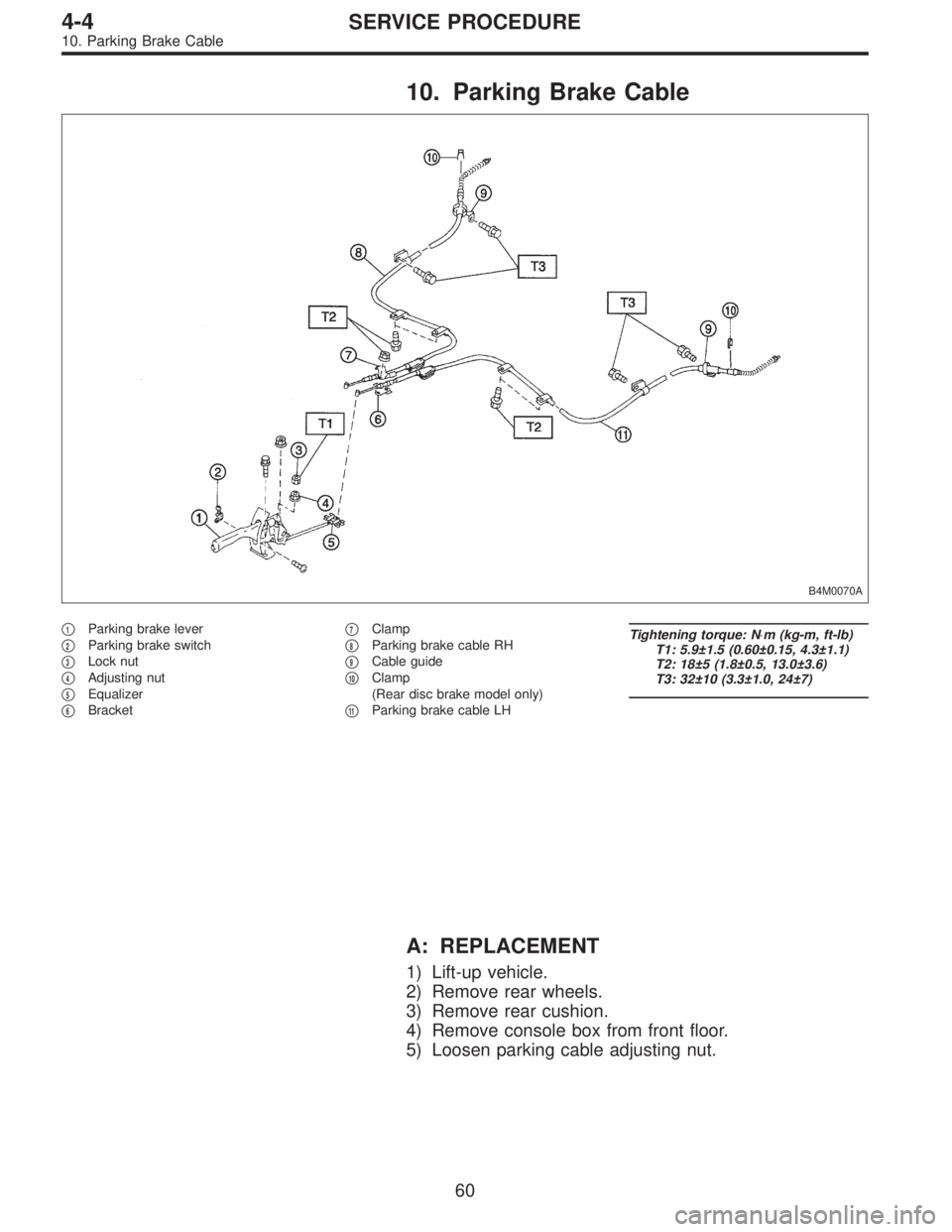
10. Parking Brake Cable
B4M0070A
�1Parking brake lever
�
2Parking brake switch
�
3Lock nut
�
4Adjusting nut
�
5Equalizer
�
6Bracket�
7Clamp
�
8Parking brake cable RH
�
9Cable guide
�
10Clamp
(Rear disc brake model only)
�
11Parking brake cable LH
Tightening torque: N⋅m (kg-m, ft-lb)
T1: 5.9±1.5 (0.60±0.15, 4.3±1.1)
T2: 18±5 (1.8±0.5, 13.0±3.6)
T3: 32±10 (3.3±1.0, 24±7)
A: REPLACEMENT
1) Lift-up vehicle.
2) Remove rear wheels.
3) Remove rear cushion.
4) Remove console box from front floor.
5) Loosen parking cable adjusting nut.
60
4-4SERVICE PROCEDURE
10. Parking Brake Cable
Page 1270 of 2890

5) Perform these steps for the brakes connecting to the
secondary chamber of master cylinder, first, and then for
the ones con")
Air bleeder tightening torque:
8±1 N⋅m (0.8±0.1 kg-m, 5.8±0.7 ft-lb)
5) Perform these steps for the brakes connecting to the
secondary chamber of master cylinder, first, and then for
the ones connecting to primary chamber. With all proce-
dures completed, fully depress the brake pedal and keep
it in that position for approximately 20 seconds to make
sure that there is no leak evident in the entire system.
G4M0436
6) Perform sequence control. (With ABS model)
4-4 [W15C1].>
7) Check the pedal stroke.
While the engine is idling, depress the brake pedal with a
490 N (50 kg, 110 lb) load and measure the distance
between the brake pedal and steering wheel. With the
brake pedal released, measure the distance between the
pedal and steering wheel again. The difference between
the two measurements must be more than specified.
Specified pedal stroke:
Without ABS
90 mm (3.54 in)
With ABS
95 mm (3.74 in)
When depressing brake pedal with a 490 N (50 kg,
110 lb) load.
(1) Models without ABS
If the distance is more than specifications, there is a
possibility that air is in the brake line. Bleed air from the
brake line.
(2) Models with ABS
If the distance is more than specifications, there is a
possibility air is in the inside of the hydraulic unit.
Therefore, air must be bled from the inside of the
hydraulic unit to the brake pipes in accordance with the
bleeding sequence control.
8) Add brake fluid to the required level (MAX. level) of
reserve tank.
9) As a final step, test run the vehicle at low speed and
apply brakes relatively hard 2 to 3 times to ensure that
brakes provide normal braking action on all four wheels
without dragging and uneven braking.
63
4-4SERVICE PROCEDURE
11. Air Bleeding (Without TCS model)
Page 1272 of 2890
 Install one end of a vinyl tube onto the air bleeder of and
insert the other end of the tube into a container to collect
the brake fluid.
6) Instruct your co-worker to depre")
G4M0434
G4M0438
G4M0435
5) Install one end of a vinyl tube onto the air bleeder of and
insert the other end of the tube into a container to collect
the brake fluid.
6) Instruct your co-worker to depress the brake pedal
slowly two or three times and then hold it depressed.
7) Loosen bleeder screw approximately 1/4 turn until a
small amount of brake fluid drains into container, and then
quickly tighten screw.
8) Repeat steps 6) and 7) above until there are no air
bubbles in drained brake fluid and new fluid flows through
vinyl tube.
CAUTION:
Add brake fluid as necessary while performing the air
bleed operation, in order to prevent the tank from run-
ning short of brake fluid.
9) After completing the bleeding operation, hold brake
pedal depressed and tighten screw and install bleeder cap.
Tightening torque (Bleeder screw):
8±1 N⋅m (0.8±0.1 kg-m, 5.8±0.7 ft-lb)
10) Bleed air from each wheel cylinder using the same
procedures as described in steps 6) through 7) above.
11) Depress brake pedal with a force of approximately 294
N (30 kg, 66 lb) and hold it there for approximately 20 sec-
onds. At this time check pedal to see if it shows any
unusual movement.
Visually inspect bleeder screws and brake pipe joints to
make sure that there is no fluid leakage.
12) Install wheels, and drive vehicle for a short distance
between 2 to 3 km (1 to 2 miles) to make sure that brakes
are operating properly.
65
4-4SERVICE PROCEDURE
12. Brake Fluid Replacement
Page 1273 of 2890
 Install the oil pressure gauges to measure the master
cylinder fluid pressure (front wheel brake fluid pressure)
and rear wheel cylinde")
G4M0440
13. Proportioning Valve
G4M0668
G4M0915
A: INSPECTION
1) Install the oil pressure gauges to measure the master
cylinder fluid pressure (front wheel brake fluid pressure)
and rear wheel cylinder fluid pressure.
2) Bleed air from the oil pressure gauges.
3) Check the master cylinder fluid pressure and rear wheel
cylinder fluid pressure.
The standard values are shown in Figure.
4) For the oil pressure in case of split point, refer to A:
SPECIFICATIONS 4-4 [S0A0].
B: REMOVAL
1) Remove brake pipe from proportioning valve at four
places.
2) Remove proportioning valve from its bracket.
CAUTION:
Do not disassemble or adjust the proportioning valve.
(The proportioning valve must be replaced as an
assembly.)
C: INSTALLATION
1) Install proportioning valve to bracket.
2) Connect brake pipes correctly to proportioning valve.
3) Bleed air, then check each joint of brake pipe for oil
leaks.
Tightening torque:
Proportioning valve to brake pipe flare nut:
15
+3
�2N⋅m (1.5+0.3
�0.2kg-m, 10.8+2.2
�1.4ft-lb)
Proportioning valve to bracket:
18±5 N⋅m (1.8±0.5 kg-m, 13.0±3.6 ft-lb)
66
4-4SERVICE PROCEDURE
13. Proportioning Valve
Page 1278 of 2890
G4M0451
4) Install front ABS sensor on strut and wheel apron
bracket.
Tightening torque:
32±10 N⋅m (3.3±1.0 kg-m, 24±7 ft-lb)
5) Place a thickness gauge between ABS sensor’s pole
piece and tone wheel’s tooth face. After standard clearance
is obtained over the entire perimeter, tighten ABS sensor
on housing to specified torque.
ABS sensor standard clearance:
0.9—1.4 mm (0.035—0.055 in)
Tightening torque:
32±10 N⋅m (3.3±1.0 kg-m, 24±7 ft-lb)
CAUTION:
Check the marks on the harness to make sure that no
distortion exists. (RH: white, LH: yellow)
NOTE:
If the clearance is outside specifications, readjust.
2. REAR ABS SENSOR
1) Install rear tone wheel on hub, then rear housing on
hub.
G4M0445
2) Temporarily install rear ABS sensor on back plate.
CAUTION:
Be careful not to strike ABS sensor’s pole piece and
tone wheel’s teeth against adjacent metal parts during
installation.
71
4-4SERVICE PROCEDURE
14. ABS Sensor
Page 1279 of 2890
3) Install rear drive shaft to rear housing and rear differen-
tial spindle.
G4M0453
4) Install rear sensor harness on rear trailing link.
Tightening torque:
32±10 N⋅m (3.3±1.0 kg-m, 24±7 ft-lb)
5) Place a thickness gauge between ABS sensor’s pole
piece and tone wheel’s tooth face. After standard clearance
is obtained over the entire perimeter, tighten ABS sensor
on back plate to specified torque.
ABS sensor standard clearance:
0.7—1.2 mm (0.028—0.047 in)
Tightening torque:
32±10 N⋅m (3.3±1.0 kg-m, 24±7 ft-lb)
CAUTION:
Check the marks on the harness to make sure that no
distortion exists. (RH: white, LH: yellow)
NOTE:
If the clearance is outside specifications, readjust.
72
4-4SERVICE PROCEDURE
14. ABS Sensor
Page 1280 of 2890

B4M0069A
�1Connector
�
2Cap
�
3Motor relay
�
4Valve relay
�
5Hydraulic control unit
�
6Front-RH outlet
�
7Rear-LH outlet�
8Rear-RH outlet
�
9Fro")
15. Hydraulic Unit for ABS System
(Except ABS 5.3 Type)
B4M0069A
�1Connector
�
2Cap
�
3Motor relay
�
4Valve relay
�
5Hydraulic control unit
�
6Front-RH outlet
�
7Rear-LH outlet�
8Rear-RH outlet
�
9Front-LH outlet
�
10Primary inlet
�
11Secondary inlet
�
12Bracket
Tightening torque: N⋅m (kg-m, ft-lb)
T1: 1.2±0.2
(0.125±0.025, 0.9±0.2)
T2: 18±5 (1.8±0.5, 13.0±3.6)
T3: 29±7 (3.0±0.7, 21.7±5.1)
T4: 32±10 (3.3±1.0, 24±7)
A: REMOVAL
1) Remove air intake duct.
2) Remove canister from engine compartment to facilitate
removal of hydraulic unit.
3) Disconnect brake pipes from hydraulic unit and plug
open joints to prevent entry of foreign particles.
G4M0455
4) Remove nuts and bolts which secure hydraulic unit, and
remove hydraulic unit from engine compartment.
CAUTION:
�Hydraulic unit cannot be disassembled. Do not
attempt to loosen bolts and nuts.
�Do not drop or bump hydraulic unit.
�Do not turn the hydraulic unit upside down or place
it on its side.
73
4-4SERVICE PROCEDURE
15. Hydraulic Unit for ABS System (Except ABS 5.3 Type)
 Remove console box from front floor.
2) Disconnect electric")
 Install front ABS sensor on strut and wheel apron
bracket.
Tightening torque:
32±10 N⋅m (3.3±1.0 kg-m, 24±7 ft-lb)
5) Place a thickness gauge between ABS sensor’s pole
piece and tone")
![SUBARU LEGACY 1996 Service Repair Manual 3) Install rear drive shaft to rear housing and rear differen-
tial spindle. <Ref. to 4-2 [W2E0].>
G4M0453
4) Install rear sensor harness on rear trailing link.
Tightening torque:
32±10 N⋅m (3.3±1](/manual-img/17/57433/w960_57433-1278.png "SUBARU LEGACY 1996 Service Repair Manual 3) Install rear drive shaft to rear housing and rear differen-
tial spindle. <Ref. to 4-2 [W2E0].>
G4M0453
4) Install rear sensor harness on rear trailing link.
Tightening torque:
32±10 N⋅m (3.3±1")