Page 2530 of 2890
WIRING DIAGRAM:
B4M1040
B4M0921
10X1CHECK SPECIFICATIONS OF ABSCM
USING SELECT MONITOR.
1) Press F,0and 0on the select monitor.
2) Read the select monitor display.
: Is an ABSCM for AT model installed on a MT
model?
: Replace ABSCM.
: Go to step10X2.
190
4-4cBRAKES [ABS 5.3 TYPE]
10. Diagnostics Chart with Select Monitor
Page 2534 of 2890
WIRING DIAGRAM:
B4M1040
194
4-4cBRAKES [ABS 5.3 TYPE]
10. Diagnostics Chart with Select Monitor
Page 2537 of 2890
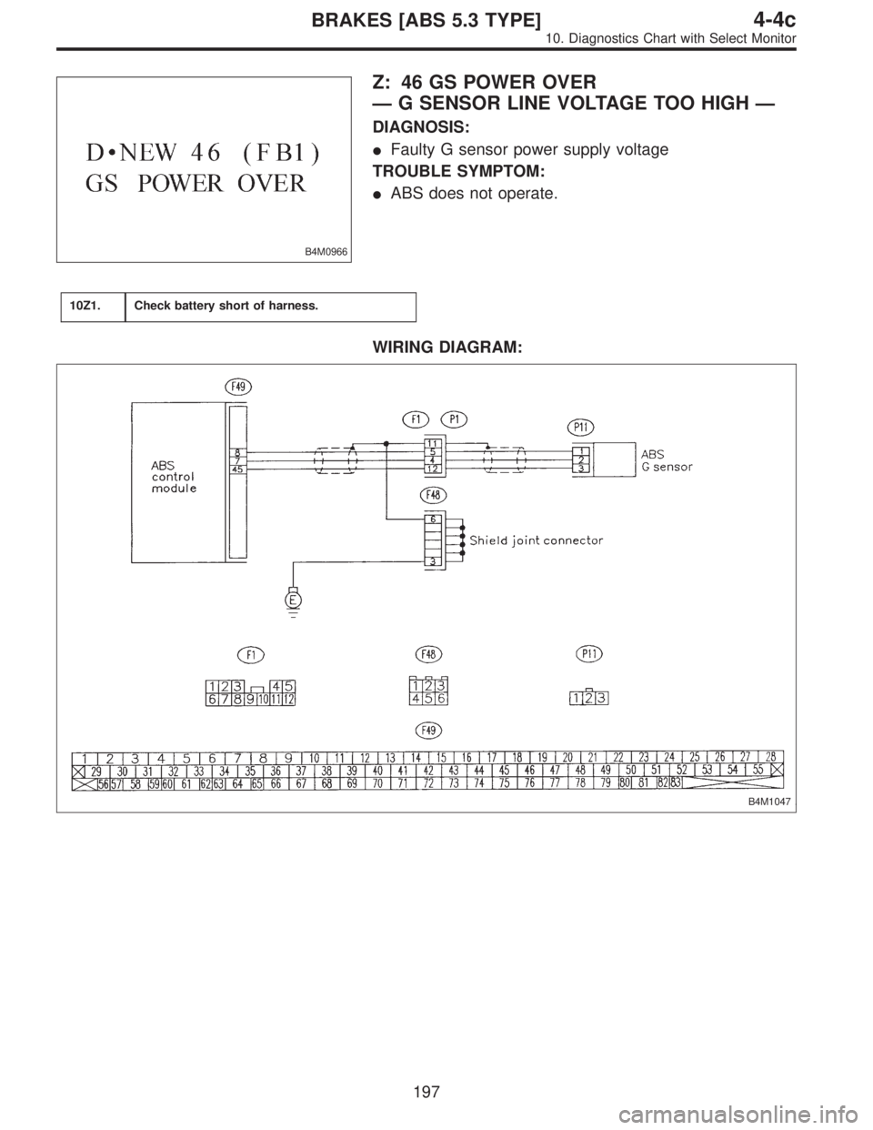
B4M0966
Z: 46 GS POWER OVER
—G SENSOR LINE VOLTAGE TOO HIGH—
DIAGNOSIS:
�Faulty G sensor power supply voltage
TROUBLE SYMPTOM:
�ABS does not operate.
10Z1.Check battery short of harness.
WIRING DIAGRAM:
B4M1047
197
4-4cBRAKES [ABS 5.3 TYPE]
10. Diagnostics Chart with Select Monitor
Page 2540 of 2890
WIRING DIAGRAM:
B4M1047
B4M0851B
10AA1
CHECK G SENSOR.
1) Turn ignition switch to OFF.
2) Remove console cover from console box.
3) Disconnect connector from G sensor.
4) Measure resistance of G sensor.
: Connector & terminal
To (P11) No. 1—No. 3
Is resistance 50±8 kΩ?
: Go to step10AA2.
: Replace G sensor.
200
4-4cBRAKES [ABS 5.3 TYPE]
10. Diagnostics Chart with Select Monitor
Page 2545 of 2890
WIRING DIAGRAM:
B4M1048
B4M0957A
10AB1
CHECK FREEZE FRAME DATA.
Press F,E,1and 5on the select monitor.
: Is the select monitor LED 5 off? Was the
ABS inactive when the problem occurred?
: Go to step10AB2.
: Go to step10AB24.
205
4-4cBRAKES [ABS 5.3 TYPE]
10. Diagnostics Chart with Select Monitor
Page 2558 of 2890
WIRING DIAGRAM:
B4M1048
B4M0858A
10AC1
CHECK RESISTANCE OF VALVE RELAY.
1) Turn ignition switch to OFF.
2) Remove valve relay from relay box.
3) Measure resistance between valve relay terminals.
: Terminals
No. 85—No. 86
Is resistance 103±10Ω?
: Go to step10AC2.
: Replace valve relay.
218
4-4cBRAKES [ABS 5.3 TYPE]
10. Diagnostics Chart with Select Monitor
Page 2566 of 2890
WIRING DIAGRAM:
B4M1049
226
4-4cBRAKES [ABS 5.3 TYPE]
10. Diagnostics Chart with Select Monitor
Page 2576 of 2890
WIRING DIAGRAM:
B4M1049
B4M0886A
10AE1
CHECK RESISTANCE OF MOTOR RELAY.
1) Turn ignition switch to OFF.
2) Remove motor relay from relay box.
3) Measure resistance between motor relay terminals.
: Terminals
No. 85—No. 86
Is resistance 80±10Ω?
: Go to step10AE2.
: Replace motor relay.
236
4-4cBRAKES [ABS 5.3 TYPE]
10. Diagnostics Chart with Select Monitor
 Press F,0and 0on the select monitor.
2) Read the select monitor display.
: Is an ABSCM for AT model installed")
![SUBARU LEGACY 1996 Service Repair Manual WIRING DIAGRAM:
B4M1040
194
4-4cBRAKES [ABS 5.3 TYPE]
10. Diagnostics Chart with Select Monitor](/manual-img/17/57433/w960_57433-2533.png "SUBARU LEGACY 1996 Service Repair Manual WIRING DIAGRAM:
B4M1040
194
4-4cBRAKES [ABS 5.3 TYPE]
10. Diagnostics Chart with Select Monitor")
 Turn ignition switch to OFF.
2) Remove console cover from console box.
3) Disconnect connector from G sensor.
4) Measure resistance of G senso")

 Turn ignition switch to OFF.
2) Remove valve relay from relay box.
3) Measure resistance between valve relay terminals.
: Ter")
![SUBARU LEGACY 1996 Service Repair Manual WIRING DIAGRAM:
B4M1049
226
4-4cBRAKES [ABS 5.3 TYPE]
10. Diagnostics Chart with Select Monitor](/manual-img/17/57433/w960_57433-2565.png "SUBARU LEGACY 1996 Service Repair Manual WIRING DIAGRAM:
B4M1049
226
4-4cBRAKES [ABS 5.3 TYPE]
10. Diagnostics Chart with Select Monitor")
 Turn ignition switch to OFF.
2) Remove motor relay from relay box.
3) Measure resistance between motor relay terminals.
: Ter")