Page 2734 of 2890
G6M0200
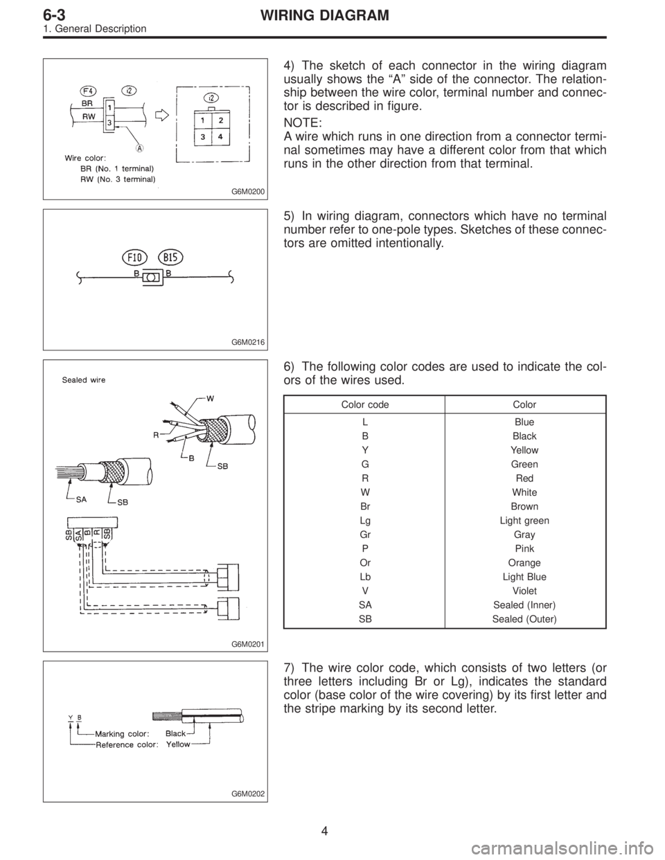
4) The sketch of each connector in the wiring diagram
usually shows the“A”side of the connector. The relation-
ship between the wire color, terminal number and connec-
tor is described in figure.
NOTE:
A wire which runs in one direction from a connector termi-
nal sometimes may have a different color from that which
runs in the other direction from that terminal.
G6M0216
5) In wiring diagram, connectors which have no terminal
number refer to one-pole types. Sketches of these connec-
tors are omitted intentionally.
G6M0201
6) The following color codes are used to indicate the col-
ors of the wires used.
Color code Color
L Blue
B Black
Y Yellow
G Green
RRed
W White
Br Brown
Lg Light green
Gr Gray
P Pink
Or Orange
Lb Light Blue
V Violet
SA Sealed (Inner)
SB Sealed (Outer)
G6M0202
7) The wire color code, which consists of two letters (or
three letters including Br or Lg), indicates the standard
color (base color of the wire covering) by its first letter and
the stripe marking by its second letter.
4
6-3WIRING DIAGRAM
1. General Description
Page 2735 of 2890
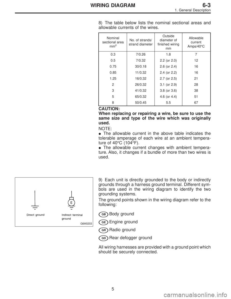
8) The table below lists the nominal sectional areas and
allowable currents of the wires.
Nominal
sectional area
mm
2
No. of strands/
strand diameterOutside
diameter of
finished wiring
mmAllowable
current
Amps/40°C
0.3 7/0.26 1.8 7
0.5 7/0.32 2.2 (or 2.0) 12
0.75 30/0.18 2.6 (or 2.4) 16
0.85 11/0.32 2.4 (or 2.2) 16
1.25 16/0.32 2.7 (or 2.5) 21
2 26/0.32 3.1 (or 2.9) 28
3 41/0.32 3.8 (or 3.6) 38
5 65/0.32 4.6 (or 4.4) 51
8 50/0.45 5.5 67
CAUTION:
When replacing or repairing a wire, be sure to use the
same size and type of the wire which was originally
used.
NOTE:
�The allowable current in the above table indicates the
tolerable amperage of each wire at an ambient tempera-
ture of 40°C (104°F).
�The allowable current changes with ambient tempera-
ture. Also, it changes if a bundle of more than two wires is
used.
G6M0203
9) Each unit is directly grounded to the body or indirectly
grounds through a harness ground terminal. Different sym-
bols are used in the wiring diagram to identify the two
grounding systems.
The ground points shown in the wiring diagram refer to the
following:
�GBBody ground
�GEEngine ground
�GRRadio ground
�GDRear defogger ground
All wiring harnesses are provided with a ground point which
should be securely connected.
5
6-3WIRING DIAGRAM
1. General Description
Page 2736 of 2890
10) Relays are classified as normally-open or normally-
closed.
The normally-closed relay has one or more contacts.
The wiring diagram shows the relay mode when the ener-
gizing circuit is OFF.
G6M0204
Key to symbols:
�→: Current flows.
X→: Current does not flow.
6
6-3WIRING DIAGRAM
1. General Description
Page 2737 of 2890
G6M0205
11) Each connector number shown in the wiring diagram
corresponds to that in the wiring harness. The location of
each connector in the actual vehicle is determined by read-
ing the first character of the connector (for example, a“F”
for F8,“i”for i16, etc.) and the type of wiring harness.
The first character of each connector number refers to the
area or system of the vehicle, as indicated in table below.
Symbol Wiring harness and Cord
F Front wiring harness
B Bulkhead wiring harness
E Engine wiring harness
T Transmission cord
D Door cord LH & RH, Rear gate cord
I Instrument panel wiring harness
RRear wiring harness, Rear defogger cord
Room light cord,
Fuel tank cord,
Sunroof cord,
Trunk lid cord
P Floor wiring harness
7
6-3WIRING DIAGRAM
1. General Description
Page 2738 of 2890
2. Basic Diagnostics Procedures
The most important purpose of diagnostics is to determine
which part is malfunctioning quickly, to save time and labor.
A: IDENTIFICATION OF TROUBLE SYMPTOM
Determine what the problem is based on the symptom.
B: PROBABLE CAUSE OF TROUBLE
Look at the wiring diagram and check the system’s circuit.
Then check the switch, relay, fuse, ground, etc.
C: LOCATION AND REPAIR OF TROUBLE
1) Using the diagnostics narrow down the causes.
2) If necessary, use a voltmeter, ohmmeter, etc.
3) Before replacing certain component parts (switch, relay,
etc.), check the power supply, ground, for open wiring
harness, poor connectors, etc. If no problems are
encountered, check the component parts.
D: CONFIRMATION OF SYSTEM OPERATION
After repairing, ensure that the system operates properly.
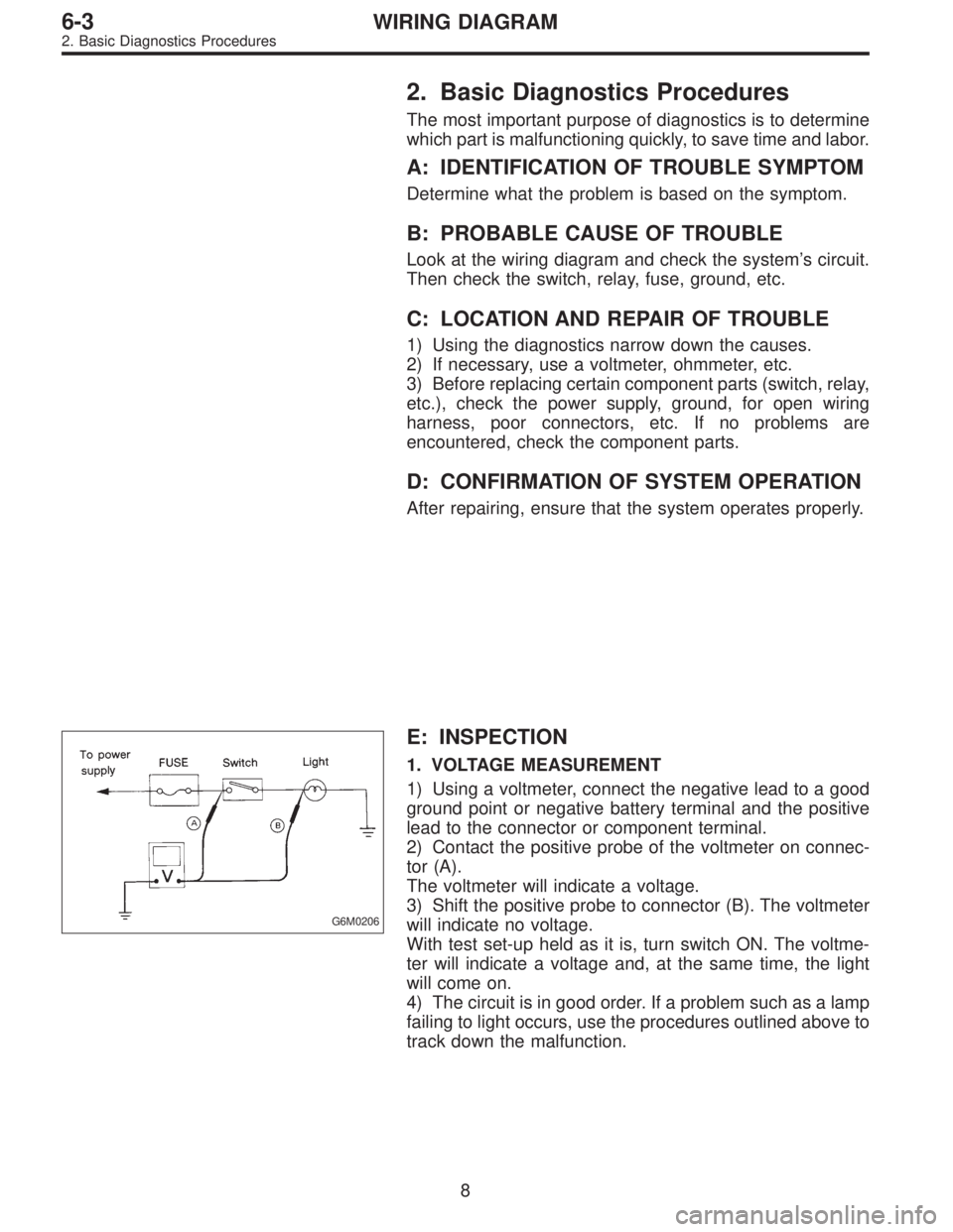
G6M0206
E: INSPECTION
1. VOLTAGE MEASUREMENT
1) Using a voltmeter, connect the negative lead to a good
ground point or negative battery terminal and the positive
lead to the connector or component terminal.
2) Contact the positive probe of the voltmeter on connec-
tor (A).
The voltmeter will indicate a voltage.
3) Shift the positive probe to connector (B). The voltmeter
will indicate no voltage.
With test set-up held as it is, turn switch ON. The voltme-
ter will indicate a voltage and, at the same time, the light
will come on.
4) The circuit is in good order. If a problem such as a lamp
failing to light occurs, use the procedures outlined above to
track down the malfunction.
8
6-3WIRING DIAGRAM
2. Basic Diagnostics Procedures
Page 2739 of 2890
G6M0207
2. CIRCUIT CONTINUITY CHECKS
1) Disconnect the battery terminal or connector so there is
no voltage between the check points.
Contact the two leads of an ohmmeter to each of the check
points.
If the circuit has diodes, reverse the two leads and check
again.
2) Use an ohmmeter to check for diode continuity.
When contacting the negative lead to the diode positive
side and the positive lead to the negative side, there should
be continuity.
When contacting the two leads in reverse, there should be
no continuity.
3) Symbol“o—o”indicates that continuity exists between
two points or terminals. For example, when a switch posi-
tion is“3”, continuity exists among terminals 1, 3 and 6, as
shown in table below.
Terminal
123456
Switch Position
OFF
1��
�
2���
3���
4���
9
6-3WIRING DIAGRAM
2. Basic Diagnostics Procedures
Page 2740 of 2890
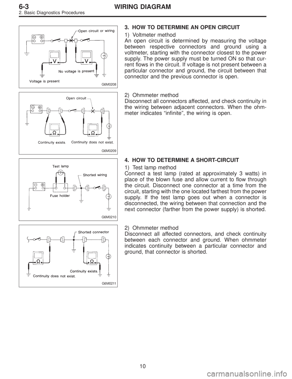
G6M0208
3. HOW TO DETERMINE AN OPEN CIRCUIT
1) Voltmeter method
An open circuit is determined by measuring the voltage
between respective connectors and ground using a
voltmeter, starting with the connector closest to the power
supply. The power supply must be turned ON so that cur-
rent flows in the circuit. If voltage is not present between a
particular connector and ground, the circuit between that
connector and the previous connector is open.
G6M0209
2) Ohmmeter method
Disconnect all connectors affected, and check continuity in
the wiring between adjacent connectors. When the ohm-
meter indicates“infinite”, the wiring is open.
G6M0210
4. HOW TO DETERMINE A SHORT-CIRCUIT
1) Test lamp method
Connect a test lamp (rated at approximately 3 watts) in
place of the blown fuse and allow current to flow through
the circuit. Disconnect one connector at a time from the
circuit, starting with the one located farthest from the power
supply. If the test lamp goes out when a connector is
disconnected, the wiring between that connection and the
next connector (farther from the power supply) is shorted.
G6M0211
2) Ohmmeter method
Disconnect all affected connectors, and check continuity
between each connector and ground. When ohmmeter
indicates continuity between a particular connector and
ground, that connector is shorted.
10
6-3WIRING DIAGRAM
2. Basic Diagnostics Procedures
Page 2741 of 2890
3. Working Precautions
1. PRECAUTIONS WHEN WORKING WITH THE
PARTS MOUNTED ON THE VEHICLE
1) When working under a vehicle which is jacked-up,
always be sure to use safety stands.
2) The parking brake must always be applied during work-
ing. Also, in automatic transmission vehicles, keep the
select lever set to the P (Parking) range.
3) Be sure the workshop is properly ventilated when run-
ning the engine. Further, be careful not to touch the belt or
fan while the engine is operating.
4) Be careful not to touch hot metal parts, especially the
radiator and exhaust system immediately after the engine
has been shut off.
2. PRECAUTIONS IN TROUBLE DIAGNOSIS AND
REPAIR OF ELECTRIC PARTS
1) The battery cable must be disconnected from the bat-
tery’s (�) terminal, and the ignition switch must be set to the
OFF position, unless otherwise required by the diagnos-
tics.
2) Securely fasten the wiring harness with clamps and
slips so that the harness does not interfere with the body
end parts or edges and bolts or screws.
3) When installing parts, be careful not to catch them on
the wiring harness.
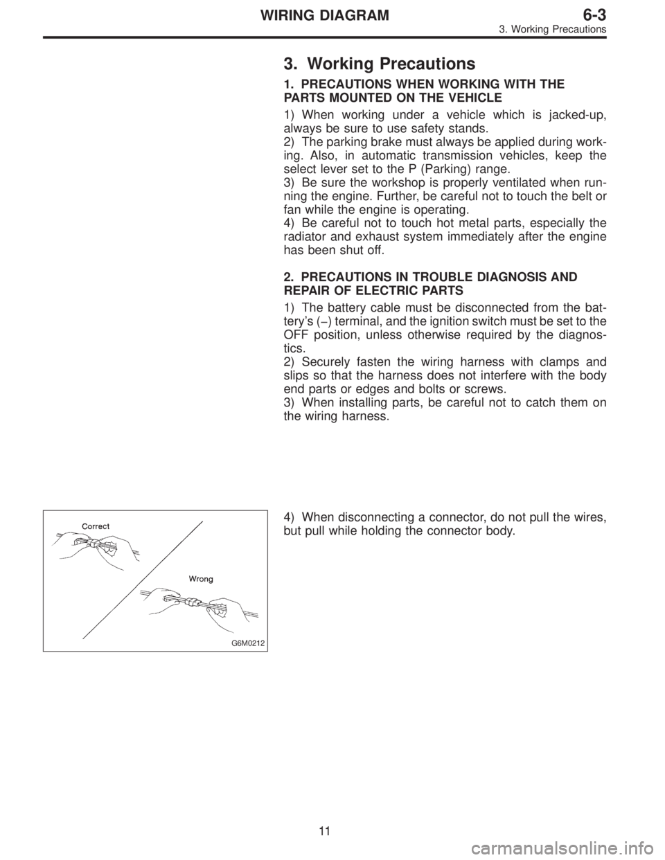
G6M0212
4) When disconnecting a connector, do not pull the wires,
but pull while holding the connector body.
11
6-3WIRING DIAGRAM
3. Working Precautions