Page 2742 of 2890
G6M0213
5) Some connectors are provided with a lock. One type of
such a connector is disconnected by pushing the lock, and
the other, by moving the lock up. In either type the lock
shape must be identified before attempting to disconnect
the connector.
To connect, insert the connector until it snaps and confirm
that it is tightly connected.
G6M0214
6) When checking continuity between connector terminals,
or measuring voltage across the terminal and ground,
always contact tester probe(s) on terminals from the wiring
connection side. If the probe is too thick to gain access to
the terminal, use“mini”test leads.
To check water-proof connectors (which are not accessible
from the wiring side), contact test probes on the terminal
side being careful not to bend or damage the terminals.
7) Sensors, relays, electrical unit, etc., are sensitive to
strong impacts.
Handle them with care so that they are not dropped or
mishandled.
12
6-3WIRING DIAGRAM
3. Working Precautions
Page 2743 of 2890
4. How to Use Wiring Diagram
B6M0213A
A: RELAY
A symbol used to indicate a relay.
B: CONNECTOR-1
The sketch of the connector indicates the one-
pole types.
C: WIRING CONNECTION
Some wiring diagrams are indicated in foldouts
for convenience. Wiring destinations are indi-
cated where necessary by corresponding sym-
bols (as when two pages are needed for clear
indication).
D: FUSE No. & RATING
The“FUSE No. & RATING”corresponds that
used in the fuse box (main fuse box, and joint
box).
E: CONNECTOR-2
1. Each connector is indicated by a symbol.
2. Each terminal number is indicated in the cor-
responding wiring diagram in an abbreviated
form.
3. For example, terminal number“C2”refers to
No. 2 terminal of connector (C:F41) shown in
the connector sketch.
13
6-3WIRING DIAGRAM
4. How to Use Wiring Diagram
Page 2744 of 2890

F: CONNECTOR SKETCH
1. Each connector sketch clearly identifies the
shape and color of a connector as well as
terminal locations. Non-colored connectors
are indicated in natural color.
2. When more than two types of connector
number are indicated in a connector sketch,
it means that the same type connectors are
used.
G: GROUND
Each grounding point can be located easily by
referring to the corresponding wiring harness.
H: DIODE
A symbol is used to indicate a diode.
I: WIRE TRACING ON EXTENDED
WIRING DIAGRAMS
For a wiring diagram extending over at least two
pages, a symbol (consisting of the same charac-
ters with arrows), as shown below, facilitates
wire tracing from one page to the next.
A)A, B)B
J: SYMBOLS OF WIRE CONNECTION
AND CROSSING
Symbol Refers to wires which are
connected and branched
at the“dot”point.
Symbol Refers to wires which are
crossed but not con-
nected.
K: POWER SUPPLY ROUTING
A symbol is used to indicate the power supply in
each wiring diagram.
“MB-5”,“MB-6”, etc., which are used as power
supply symbols throughout the text, correspond
with those shown in the POWER SUPPLY
ROUTING in the wiring diagram.
Accordingly, using the POWER SUPPLY ROUT-
ING and wiring diagrams permits service per-
sonnel to understand the entire electrical
arrangement of a system.
L: S.M.J.
A symbol is used to indicate the terminal
arrangement of the super multiple junction. The
S.M.J. is not shown in respective wiring dia-
grams but is indicated on the next page.
SYMBOLS AND ABBREVIATIONS
A number of symbols and abbreviations are used
in each wiring diagram to easily identify parts or
circuits.
14
6-3WIRING DIAGRAM
4. How to Use Wiring Diagram
Page 2745 of 2890
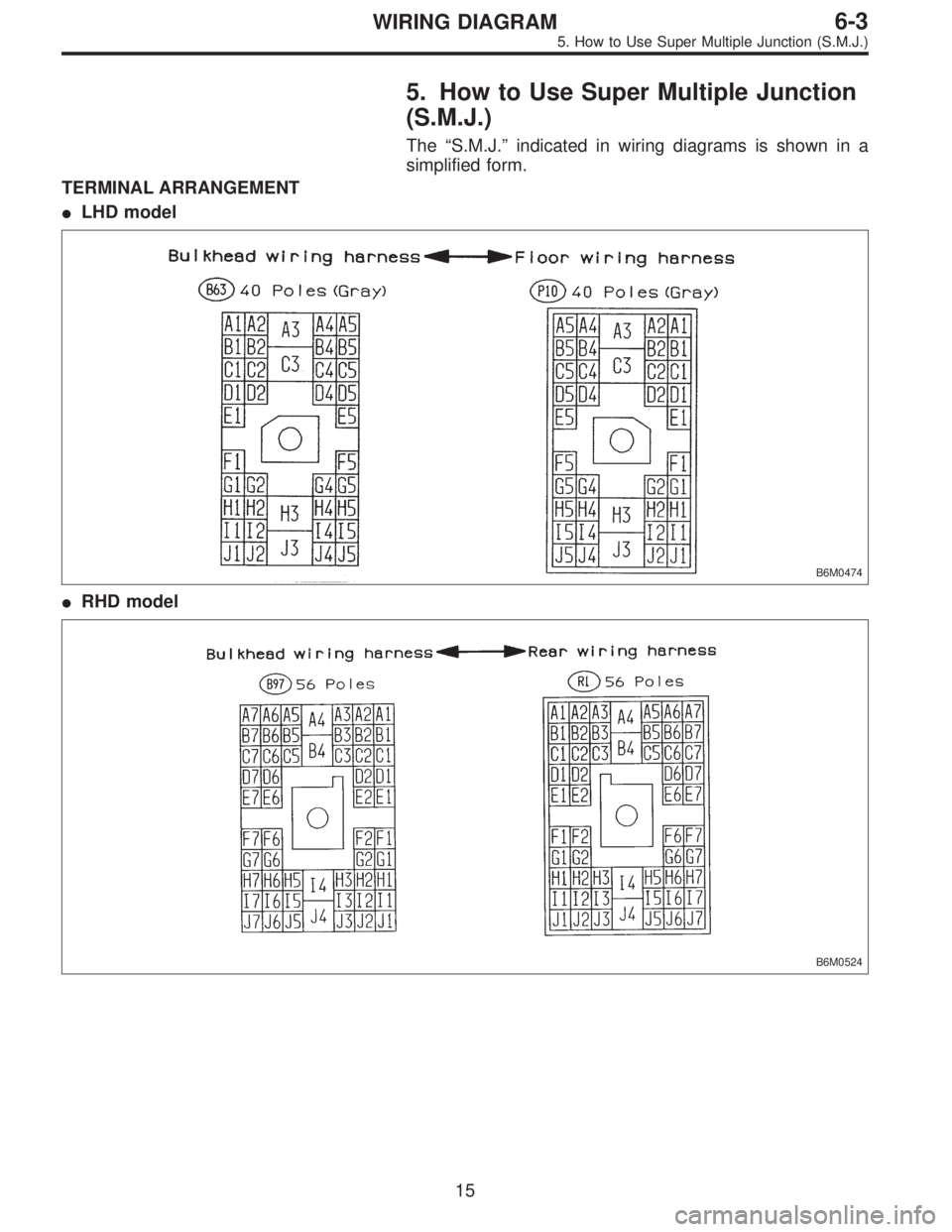
5. How to Use Super Multiple Junction
(S.M.J.)
The“S.M.J.”indicated in wiring diagrams is shown in a
simplified form.
TERMINAL ARRANGEMENT
�LHD model
B6M0474
�RHD model
B6M0524
15
6-3WIRING DIAGRAM
5. How to Use Super Multiple Junction (S.M.J.)
Page 2746 of 2890
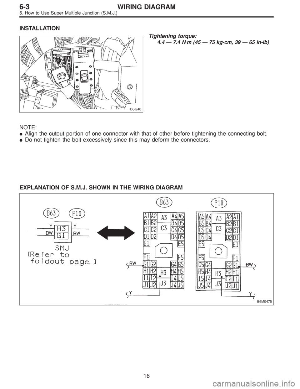
INSTALLATION
B6-240
Tightening torque:
4.4 — 7.4 N⋅m (45 — 75 kg-cm, 39 — 65 in-lb)
NOTE:
�Align the cutout portion of one connector with that of other before tightening the connecting bolt.
�Do not tighten the bolt excessively since this may deform the connectors.
EXPLANATION OF S.M.J. SHOWN IN THE WIRING DIAGRAM
B6M0475
16
6-3WIRING DIAGRAM
5. How to Use Super Multiple Junction (S.M.J.)
Page 2747 of 2890
ABBREVIATION LIST
Abbr. Full name
A.B.S. Antilock Brake System
ACC Accessory
A/C Air Conditioning
AD Auto Down
AT Automatic Transmission
AU Auto Up
+B Battery
DN Down
DRL Daytime Running Light
E Ground
F/B Fuse & Joint Box
FL1.5 Fusible link 1.5 mm
2
IG Ignition
Illumi. Illumination
Abbr. Full name
LH Left Hand
Lo Low
M Motor
M/B Main Fuse Box
MG Magnet
Mi Middle
OP Optional Parts
PASS Passing
RH Right Hand
SBF Slow Blow Fuse
S.M.J. Super Multiple Junction
ST Starter
SW Switch
T.C.S. Traction Control System
UP Up
WASH Washer
17
6-3WIRING DIAGRAM
5. How to Use Super Multiple Junction (S.M.J.)
Page 2748 of 2890
6. Wiring Diagram
1. POWER SUPPLY ROUTING
�LHD model
BU01-01A
18
6-3WIRING DIAGRAM
6. Wiring Diagram
Page 2749 of 2890
BU01-01B
19
6-3WIRING DIAGRAM
6. Wiring Diagram
 Some connectors are provided with a lock. One type of
such a connector is disconnected by pushing the lock, and
the other, by moving the lock up. In either type the lock
shape must be ident")