Page 2583 of 2890
WIRING DIAGRAM:
B4M1049
243
4-4cBRAKES [ABS 5.3 TYPE]
10. Diagnostics Chart with Select Monitor
Page 2588 of 2890
WIRING DIAGRAM:
B4M1041
248
4-4cBRAKES [ABS 5.3 TYPE]
10. Diagnostics Chart with Select Monitor
Page 2593 of 2890
WIRING DIAGRAM:
B4M1050
B4M0921
10AH1CHECK SPECIFICATIONS OF ABSCM
USING SELECT MONITOR.
1) Press F,0and 0on the select monitor.
2) Read the select monitor display.
: Is an ABSCM for 4WD model installed on a
FWD model?
: Replace ABSCM.
: Go to step10AH2.
253
4-4cBRAKES [ABS 5.3 TYPE]
10. Diagnostics Chart with Select Monitor
Page 2600 of 2890
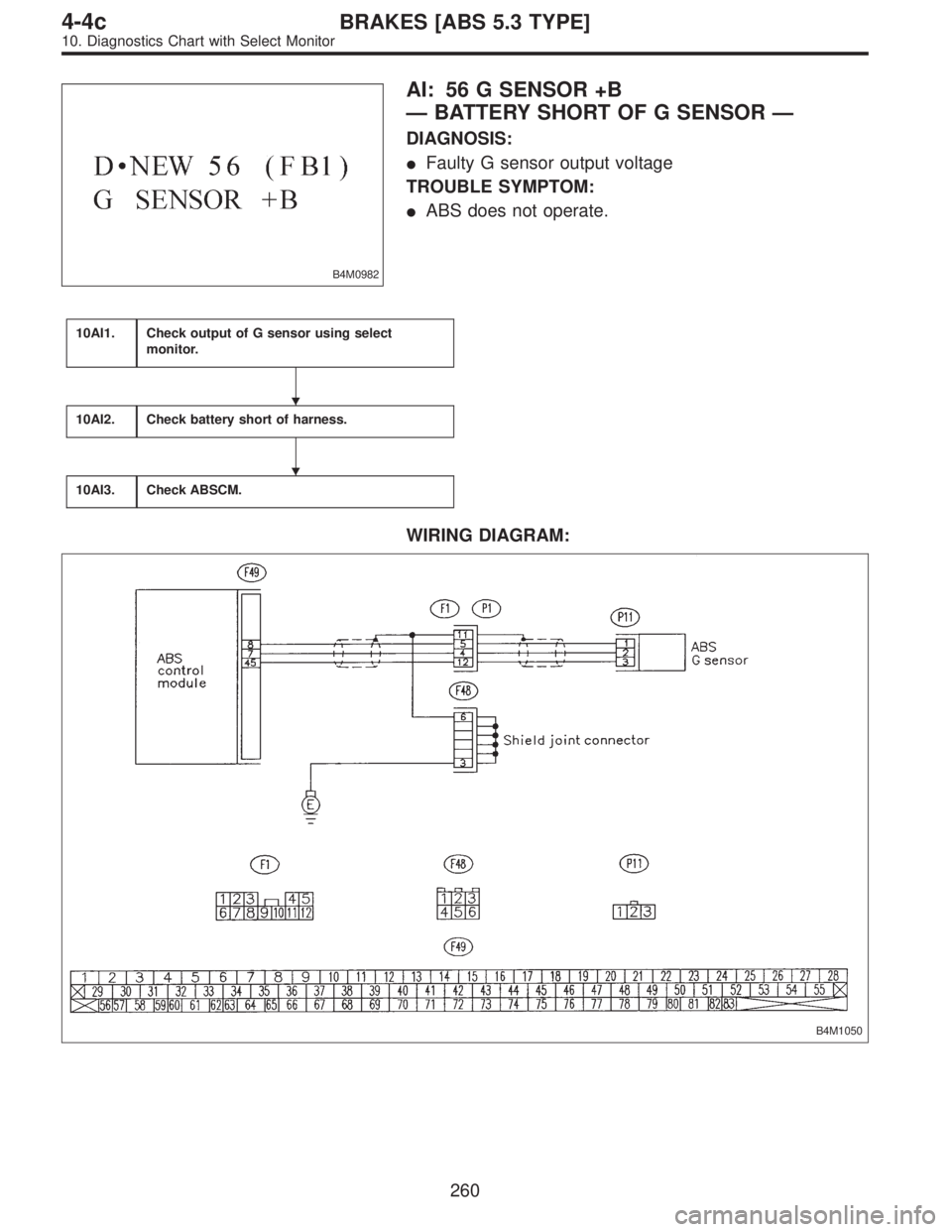
B4M0982
AI: 56 G SENSOR +B
—BATTERY SHORT OF G SENSOR—
DIAGNOSIS:
�Faulty G sensor output voltage
TROUBLE SYMPTOM:
�ABS does not operate.
10AI1.Check output of G sensor using select
monitor.
10AI2.Check battery short of harness.
10AI3.Check ABSCM.
WIRING DIAGRAM:
B4M1050
�
�
260
4-4cBRAKES [ABS 5.3 TYPE]
10. Diagnostics Chart with Select Monitor
Page 2603 of 2890
WIRING DIAGRAM:
B4M1050
B4M0927
10AJ1CHECK OUTPUT OF G SENSOR USING
SELECT MONITOR.
1) Press F,1and 0on the select monitor.
2) Read the select monitor display.
: Is the indicated reading 2.3±0.2 V when the
G sensor is in horizontal position?
: Go to step10AJ2.
: Go to step10AJ5.
10AJ2CHECK POOR CONTACT IN CONNEC-
TOR BETWEEN ABSCM AND G SENSOR.
: Is there poor contact in connector between
ABSCM and G sensor?
: Repair connector.
: Go to step10AJ3.
263
4-4cBRAKES [ABS 5.3 TYPE]
10. Diagnostics Chart with Select Monitor
Page 2607 of 2890
WIRING DIAGRAM:
B4M1050
10AK1CHECK ALL FOUR WHEELS FOR FREE
TURNING.
: Have the wheels been turned freely such as
when the vehicle is lifted up, or operated on
a rolling road?
: The ABS is normal. Erase the trouble code.
: Go to step10AK2.
B4M0927
10AK2CHECK OUTPUT OF G SENSOR USING
SELECT MONITOR.
1) Press F,1and 0on the select monitor.
2) Read the select monitor display.
: Is the indicated reading 2.3±0.2 V when the
vehicle is in horizontal position?
: Go to next step.
: Go to step10AK5.
267
4-4cBRAKES [ABS 5.3 TYPE]
10. Diagnostics Chart with Select Monitor
Page 2732 of 2890
1. General Description
1. HOW TO USE THIS MANUAL
The description of the electrical system is divided into the
charging system, starting system, etc.
1) First, open to the necessary electrical system section
and wiring diagram.
2) Next, open the foldout page of the electrical wiring dia-
gram. By observing the electrical wiring harness’ illustra-
tions (front, instrument panel, etc.), the wiring diagram con-
nector can be located.
G6M0192
G6M0193
2. WIRING DIAGRAM
The wiring diagram of each system is illustrated so that you
can understand the path through which the electric current
flows from the battery.
Sketches and codes are used in the diagrams. They should
read as follows:
1) Each connector and its terminal position are indicated
by a sketch of the connector in a disconnected state which
is viewed from the front, as shown in figure.
2
6-3WIRING DIAGRAM
1. General Description
Page 2733 of 2890
 The number of poles or pins, presence of a lock, and pin
number of each terminal are indicated in the sketch of each
connector.
In the sketch, the highest pole number refers to the num-
ber of pole")
2) The number of poles or pins, presence of a lock, and pin
number of each terminal are indicated in the sketch of each
connector.
In the sketch, the highest pole number refers to the num-
ber of poles which the connector has. For example, the
sketch of the connector shown in figure indicates the con-
nector has 9 poles.
Connector used in vehicleConnector shown in wiring diagram
Sketch Symbol Number of poles
G6M0194G6M0196
G6M0198
Numbered in order from
upper right to lower left.
G6M0195G6M0197
Numbered in order from
upper left to lower right.
G6M0199
When one set of connectors is viewed from the front side,
the pole numbers of one connector are symmetrical to
those of the other. When these two connectors are con-
nected as a unit, the poles which have the same number
are joined.
3) Electrical wiring harness
The connectors are numbered along with the number of
poles, external colors, and mating connections in the
accompanying list.
3
6-3WIRING DIAGRAM
1. General Description
![SUBARU LEGACY 1996 Service Repair Manual WIRING DIAGRAM:
B4M1049
243
4-4cBRAKES [ABS 5.3 TYPE]
10. Diagnostics Chart with Select Monitor](/manual-img/17/57433/w960_57433-2582.png "SUBARU LEGACY 1996 Service Repair Manual WIRING DIAGRAM:
B4M1049
243
4-4cBRAKES [ABS 5.3 TYPE]
10. Diagnostics Chart with Select Monitor")
![SUBARU LEGACY 1996 Service Repair Manual WIRING DIAGRAM:
B4M1041
248
4-4cBRAKES [ABS 5.3 TYPE]
10. Diagnostics Chart with Select Monitor](/manual-img/17/57433/w960_57433-2587.png "SUBARU LEGACY 1996 Service Repair Manual WIRING DIAGRAM:
B4M1041
248
4-4cBRAKES [ABS 5.3 TYPE]
10. Diagnostics Chart with Select Monitor")
 Press F,0and 0on the select monitor.
2) Read the select monitor display.
: Is an ABSCM for 4WD model install")
 Press F,1and 0on the select monitor.
2) Read the select monitor display.
: Is the indicated reading 2.3±0.2 V wh")

 First, open to the necessary electrical system s")