Page 617 of 2890
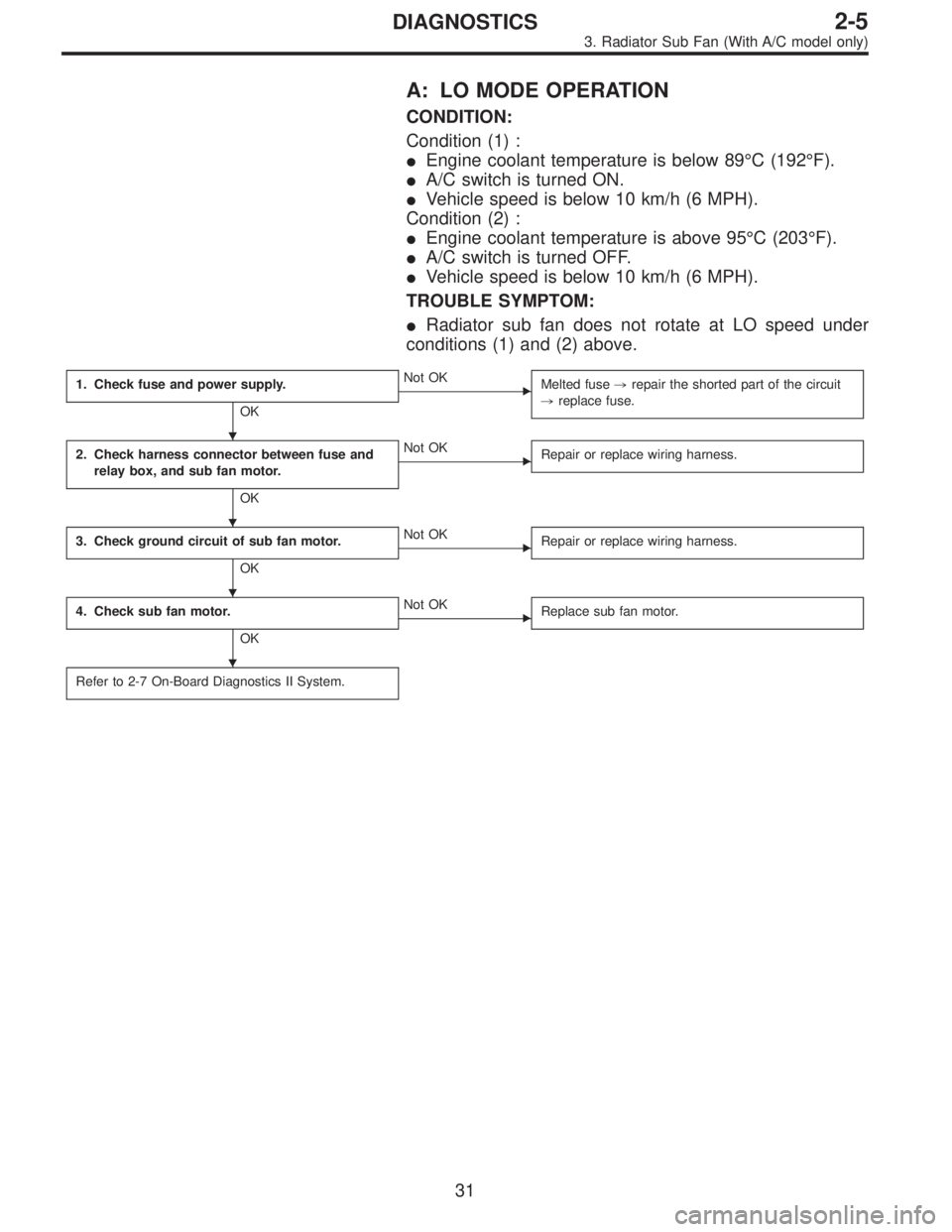
A: LO MODE OPERATION
CONDITION:
Condition (1) :
�Engine coolant temperature is below 89°C (192°F).
�A/C switch is turned ON.
�Vehicle speed is below 10 km/h (6 MPH).
Condition (2) :
�Engine coolant temperature is above 95°C (203°F).
�A/C switch is turned OFF.
�Vehicle speed is below 10 km/h (6 MPH).
TROUBLE SYMPTOM:
�Radiator sub fan does not rotate at LO speed under
conditions (1) and (2) above.
1. Check fuse and power supply.
OK
�Not OK
Melted fuse,repair the shorted part of the circuit
,replace fuse.
2. Check harness connector between fuse and
relay box, and sub fan motor.
OK
�Not OK
Repair or replace wiring harness.
3. Check ground circuit of sub fan motor.
OK
�Not OK
Repair or replace wiring harness.
4. Check sub fan motor.
OK
�Not OK
Replace sub fan motor.
Refer to 2-7 On-Board Diagnostics II System.
�
�
�
�
31
2-5DIAGNOSTICS
3. Radiator Sub Fan (With A/C model only)
Page 618 of 2890
 Check fuse No. 13.
2) Turn ignition switch to ACC.
3) Measure voltage between fuse and relay box, and body.
Connector & terminal / Specified voltage:
(F40)")
B2M0427A
1. CHECK FUSE AND POWER SUPPLY.
1) Check fuse No. 13.
2) Turn ignition switch to ACC.
3) Measure voltage between fuse and relay box, and body.
Connector & terminal / Specified voltage:
(F40) No. 3—Body / 10 V, or more
B2M0377A
2. CHECK HARNESS CONNECTOR BETWEEN FUSE
AND RELAY BOX, AND SUB FAN MOTOR.
1) Turn ignition switch to OFF.
2) Disconnect connectors from fuse and relay box, and
sub fan motor.
3) Measure resistance of harness connector between fuse
and relay box, and sub fan motor.
Connector & terminal / Specified resistance:
(F40) No. 3—(F16) No. 2 / 10Ω, max.
B2M0378A
3. CHECK GROUND CIRCUIT OF SUB FAN MOTOR.
Measure resistance between sub fan motor connector and
body.
Connector & terminal / Specified resistance:
(F16) No. 1—Body / 10Ω, max.
B2M0372A
4. CHECK SUB FAN MOTOR.
1) Disconnect connector from sub fan motor.
2) Connect battery positive (+) terminal to terminal No. 2
and connect terminal No. 1 to ground. Ensure that fan
rotates at LO speed.
32
2-5DIAGNOSTICS
3. Radiator Sub Fan (With A/C model only)
Page 619 of 2890
 :
�Engine coolant temperature is below 89°C (192°F).
�A/C switch is turned ON.
�Vehicle speed is over 20 km/h (12 MPH).
Condition (2) :
�Engine coolant")
B: HI MODE OPERATION
CONDITION:
Condition (1) :
�Engine coolant temperature is below 89°C (192°F).
�A/C switch is turned ON.
�Vehicle speed is over 20 km/h (12 MPH).
Condition (2) :
�Engine coolant temperature is above 95°C (203°F).
�A/C switch is turned OFF.
�Vehicle speed is over 20 km/h (12 MPH).
Condition (3) :
�Engine coolant temperature is above 95°C (203°F).
�A/C switch is turned ON.
TROUBLE SYMPTOM:
�Radiator sub fan does not rotate at HI speed under con-
ditions (1), (2) and (3) above.
1. Check operation of sub fan motor LO mode.
OK
�Not OK
Check LO mode operation.
2. Check power supply to sub fan relay-2.
OK
�Not OK
Melted fuse (in A/C relay holder),repair the
shorted part of the circuit,replace fuse.
3. Check sub fan relay-2.
OK
�Not OK
Replace sub fan relay-2.
4. Check harness connector between sub fan
relay-2 and sub fan motor.
OK
�Not OK
Repair or replace wiring harness.
5. Check ground circuit of sub fan motor.
OK
�Not OK
Repair or replace wiring harness.
6. Check sub fan motor.
OK
�Not OK
Replace sub fan motor.
Refer to 2-7 On-Board Diagnostics II System.
�
�
�
�
�
�
33
2-5DIAGNOSTICS
3. Radiator Sub Fan (With A/C model only)
Page 620 of 2890
![SUBARU LEGACY 1996 Service Repair Manual 1. CHECK OPERATION OF SUB FAN MOTOR LO
MODE.
Check that radiator sub fan rotates at LO speed under each
condition described under LO mode operation. <Ref. to 2-5
[K3A0].>
B2M0379A
2. CHECK POWER SUPPL](/manual-img/17/57433/w960_57433-619.png "SUBARU LEGACY 1996 Service Repair Manual 1. CHECK OPERATION OF SUB FAN MOTOR LO
MODE.
Check that radiator sub fan rotates at LO speed under each
condition described under LO mode operation. <Ref. to 2-5
[K3A0].>
B2M0379A
2. CHECK POWER SUPPL")
1. CHECK OPERATION OF SUB FAN MOTOR LO
MODE.
Check that radiator sub fan rotates at LO speed under each
condition described under LO mode operation.
[K3A0].>
B2M0379A
2. CHECK POWER SUPPLY TO SUB FAN RELAY-2.
1) Turn ignition switch to OFF.
2) Disconnect connector from A/C relay holder.
3) Measure voltage between A/C relay holder connector
and body.
Connector & terminal / Specified voltage:
(F29) No. 1—Body / 1 V, max.
(F29) No. 2—Body / 1 V, max.
4) Turn ignition switch to ON.
5) Measure voltage between A/C relay holder connector
and body.
Connector & terminal / Specified voltage:
(F29) No. 1—Body / 10 V, or more
(F29) No. 2—Body / 10 V, or more
B2M0370A
3. CHECK SUB FAN RELAY-2.
1) Turn ignition switch to OFF.
2) Remove sub fan relay-2 from A/C relay holder.
3) Check continuity between terminals (indicated in table
below) when terminal (1) is connected to battery and ter-
minal (3) is grounded.
When current flows.Between terminals (2)
and (4)Continuity exists.
When current does not
flow.Between terminals (2)
and (4)Continuity does not
exist.
Between terminals (1)
and (3)Continuity exists.
34
2-5DIAGNOSTICS
3. Radiator Sub Fan (With A/C model only)
Page 621 of 2890
B2M0397A
4. CHECK HARNESS CONNECTOR BETWEEN SUB
FAN RELAY-2 AND SUB FAN MOTOR.
1) Disconnect connectors from sub fan relay-2 and sub fan
motor.
2) Measure resistance of harness connector between sub
fan relay-2 and sub fan motor.
Connector & terminal / Specified resistance:
(F29) No. 4—(F16) No. 3 / 10Ω, max.
B2M0398A
5. CHECK GROUND CIRCUIT OF SUB FAN MOTOR.
Measure resistance between sub fan motor connector and
body.
Connector & terminal / Specified resistance:
(F16) No. 1—Body / 10Ω, max.
B2M0368A
6. CHECK SUB FAN MOTOR.
1) Disconnect connector from sub fan motor.
2) Connect battery positive (+) terminal to terminals No. 2
and No.3, and connect terminal No. 1 to ground. Ensure
that fan rotates at HI speed.
35
2-5DIAGNOSTICS
3. Radiator Sub Fan (With A/C model only)
Page 657 of 2890
G6M0095
16. Main Relay
A: REMOVAL AND INSTALLATION
1) Disconnect battery ground cable.
B5M0024A
2) Remove lower cover and then disconnect connectors.
3) Lower transmission control module.
4) Remove the front pillar lower trim.
5) Remove fuse box mounting nuts.
6) Lower fuse box.
7) Remove fuse box mounting bracket.
G2M0438
8) Remove screw which retains bracket of main relay�1
and fuel pump relay�2.
9) Disconnect connector from main relay.
G2M0438
10) Installation is in the reverse order of removal.
�
1Main relay
�
2Fuel pump relay
30
2-7SERVICE PROCEDURE
16. Main Relay
Page 658 of 2890
G6M0095
17. Fuel Pump Relay
A: REMOVAL AND INSTALLATION
1) Disconnect battery ground cable.
B5M0024A
2) Remove lower cover and then disconnect connectors.
3) Lower transmission control module.
4) Remove the front pillar lower trim.
5) Remove fuse box mounting nuts.
6) Lower fuse box.
7) Remove fuse box mounting bracket.
G2M0438
8) Remove fuel pump relay from main relay and fuel pump
relay mounting bracket.
9) Disconnect connector from fuel pump relay.
G2M0438
10) Installation is in the reverse order of removal.
�
1Main relay
�
2Fuel pump relay
31
2-7SERVICE PROCEDURE
17. Fuel Pump Relay
Page 911 of 2890

6. Control Valve Body
The control valve is composed of parts which are accu-
rately machined to a high degree and should be handled
carefully during disassembly and assembly. As these parts
are similar in shape, they should be arranged in neat order
on a table after disassembly so that they can be easily
installed to their original positions. Spring loaded parts
should be also handled carefully, as springs may jump out
of place when the parts are disassembled or removed.
Extreme care should be taken so as not to drop valves on
the floor. Before assembling, the parts and valves should
be dipped in a container filled with the ATF. Make sure that
the valves are clean and free from any foreign material
before assembly. Torque specifications should also be
observed.
G3M0899
�1Lock-up control sleeve
�
2Lock-up control plug
�
3Lock-up control valve
�
4Pilot valve
�
5Pressure regulator valve
�
6Pressure regulator plug
�
7Torque converter regulation valve
�
8Pressure regulator sleeve plug
�
9Accumulator control sleeve
�
10Accumulator control plug
�
11Shuttle duty shift valve
�
124-2 sequence valve
�
13Pressure modifier valve
�
14Shift valve B
�
154-2 relay valve
�
16Shift valve A
�
17Overrunning clutch control valve�
18Overrunning clutch reducing valve
�
19Shuttle shift valve
�
20Manual valve
�
21Forward clutch control valve
�
221st reducing valve
�
233-2 timing valve
�
24Servo charger valve
�
25Pressure regulator spring
�
26Pressure modifier spring
�
27Modifier accumulator spring
�
28Pilot spring
�
29Accumulator control spring
�
30Shift B spring
�
31Shift A spring
�
32Shuttle shift spring
�
33Overrunning clutch control spring
�
344-2 sequence spring�
354-2 relay spring
�
36Servo charger spring
�
373-2 timing spring
�
381st reducing spring
�
39Overrunning clutch reducing spring
�
40Torque converter regulator spring
�
41Lock-up control spring
�
42Shuttle duty shift spring
85
3-2SERVICE PROCEDURE
6. Control Valve Body
 Disconnect connectors from sub fan relay-2 and sub fan
motor.
2) Measure resistance of harness connector between sub
f")
 Disconnect battery ground cable.
B5M0024A
2) Remove lower cover and then disconnect connectors.
3) Lower transmission control module.
4) Remove th")
 Disconnect battery ground cable.
B5M0024A
2) Remove lower cover and then disconnect connectors.
3) Lower transmission control module.
4) Remo")