Page 1329 of 2890
B4M1031A
2) Secure relay box connector to connector bracket.
CAUTION:
Align connector with mating receptacle.
3) Using cable clip, secure hydraulic unit harness to relay
box harness.
CAUTION:
Make sure hydraulic unit harness band is secured
beneath cable clip.
4) Connect connector to relay box.
5) Install canister.
6) Install air intake duct.
7) Connect ground cable to battery.
B4M1002
23. ABS Control Module (ABS 5.3 Type)
A: REMOVAL
1. LHD MODEL
1) Turn ignition switch to OFF.
2) Remove front pillar lower trim.
3) Remove glove box.
4) Remove glove box bracket.
B4M1003
5) Remove pocket back panel.
B4M1004
6) Remove bolt from bracket.
11 9
4-4SERVICE PROCEDURE
22. Hydraulic Unit for ABS System (ABS 5.3 Type) - 23. ABS Control Module (ABS 5.3 Type)
Page 1330 of 2890
B4M1031A
2) Secure relay box connector to connector bracket.
CAUTION:
Align connector with mating receptacle.
3) Using cable clip, secure hydraulic unit harness to relay
box harness.
CAUTION:
Make sure hydraulic unit harness band is secured
beneath cable clip.
4) Connect connector to relay box.
5) Install canister.
6) Install air intake duct.
7) Connect ground cable to battery.
B4M1002
23. ABS Control Module (ABS 5.3 Type)
A: REMOVAL
1. LHD MODEL
1) Turn ignition switch to OFF.
2) Remove front pillar lower trim.
3) Remove glove box.
4) Remove glove box bracket.
B4M1003
5) Remove pocket back panel.
B4M1004
6) Remove bolt from bracket.
11 9
4-4SERVICE PROCEDURE
22. Hydraulic Unit for ABS System (ABS 5.3 Type) - 23. ABS Control Module (ABS 5.3 Type)
Page 1376 of 2890
1. Air Conditioning System
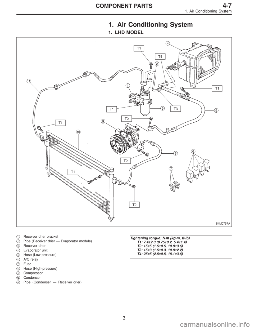
1. LHD MODEL
B4M0757A
�1Receiver drier bracket
�
2Pipe (Receiver drier—Evaporator module)
�
3Receiver drier
�
4Evaporator unit
�
5Hose (Low-pressure)
�
6A/C relay
�
7Fuse
�
8Hose (High-pressure)
�
9Compressor
�
10Condenser
�
11Pipe (Condenser—Receiver drier)
Tightening torque: N⋅m (kg-m, ft-lb)
T1: 7.4±2.0 (0.75±0.2, 5.4±1.4)
T2: 15±5 (1.5±0.5, 10.8±3.6)
T3: 15±3 (1.5±0.3, 10.8±2.2)
T4: 25±5 (2.5±0.5, 18.1±3.6)
3
4-7COMPONENT PARTS
1. Air Conditioning System
Page 1377 of 2890
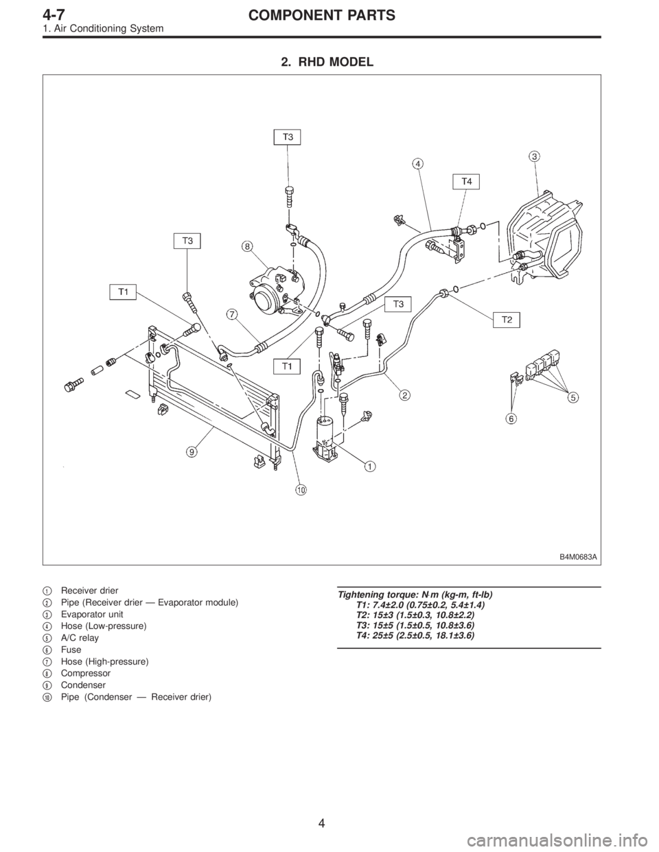
2. RHD MODEL
B4M0683A
�1Receiver drier
�
2Pipe (Receiver drier—Evaporator module)
�
3Evaporator unit
�
4Hose (Low-pressure)
�
5A/C relay
�
6Fuse
�
7Hose (High-pressure)
�
8Compressor
�
9Condenser
�
10Pipe (Condenser—Receiver drier)
Tightening torque: N⋅m (kg-m, ft-lb)
T1: 7.4±2.0 (0.75±0.2, 5.4±1.4)
T2: 15±3 (1.5±0.3, 10.8±2.2)
T3: 15±5 (1.5±0.5, 10.8±3.6)
T4: 25±5 (2.5±0.5, 18.1±3.6)
4
4-7COMPONENT PARTS
1. Air Conditioning System
Page 1415 of 2890
![SUBARU LEGACY 1996 Service Repair Manual B4M0103
B4M0764
16. Flexible Hose
A: REMOVAL AND INSTALLATION
1) Disconnect battery negative terminal.
2) Discharge refrigerant using refrigerant recovery system.
<Ref. to 4-7 [W601].>
3) Remove low-p](/manual-img/17/57433/w960_57433-1414.png "SUBARU LEGACY 1996 Service Repair Manual B4M0103
B4M0764
16. Flexible Hose
A: REMOVAL AND INSTALLATION
1) Disconnect battery negative terminal.
2) Discharge refrigerant using refrigerant recovery system.
<Ref. to 4-7 [W601].>
3) Remove low-p")
B4M0103
B4M0764
16. Flexible Hose
A: REMOVAL AND INSTALLATION
1) Disconnect battery negative terminal.
2) Discharge refrigerant using refrigerant recovery system.
3) Remove low-pressure hose.
(1) Remove hose attaching bolts.
CAUTION:
Plug the opening to prevent foreign matter from get-
ting in.
(2) Disconnect the connector at evaporator module.
4) Remove high-pressure hose.
(1) Disconnect hose attaching bolt (compressor side).
(2) Disconnect hose attaching bolt (condenser side).
CAUTION:
Plug the opening to prevent foreign matter from get-
ting in.
5) Installation is in the reverse order of removal.
6) Charge refrigerant.
G4M0649
17. Relay and Fuse
A: LOCATION
Relays used with A/C system are located as shown in fig-
ure.
1) A/C relay
2) Main fan (radiator fan) relay
3) Sub fan (condenser fan) relay
4) Sub fan (condenser fan) water temperature relay
5) Fuses (10 A and 20 A)
G4M0651
B: INSPECTION
1) Check conduction with a circuit tester (ohm range)
according to the following table in figure.
B4M0105A
2) Replace relays which do not meet specifications.
39
4-7SERVICE PROCEDURE
16. Flexible Hose - 17. Relay and Fuse
Page 1416 of 2890
![SUBARU LEGACY 1996 Service Repair Manual B4M0103
B4M0764
16. Flexible Hose
A: REMOVAL AND INSTALLATION
1) Disconnect battery negative terminal.
2) Discharge refrigerant using refrigerant recovery system.
<Ref. to 4-7 [W601].>
3) Remove low-p](/manual-img/17/57433/w960_57433-1415.png "SUBARU LEGACY 1996 Service Repair Manual B4M0103
B4M0764
16. Flexible Hose
A: REMOVAL AND INSTALLATION
1) Disconnect battery negative terminal.
2) Discharge refrigerant using refrigerant recovery system.
<Ref. to 4-7 [W601].>
3) Remove low-p")
B4M0103
B4M0764
16. Flexible Hose
A: REMOVAL AND INSTALLATION
1) Disconnect battery negative terminal.
2) Discharge refrigerant using refrigerant recovery system.
3) Remove low-pressure hose.
(1) Remove hose attaching bolts.
CAUTION:
Plug the opening to prevent foreign matter from get-
ting in.
(2) Disconnect the connector at evaporator module.
4) Remove high-pressure hose.
(1) Disconnect hose attaching bolt (compressor side).
(2) Disconnect hose attaching bolt (condenser side).
CAUTION:
Plug the opening to prevent foreign matter from get-
ting in.
5) Installation is in the reverse order of removal.
6) Charge refrigerant.
G4M0649
17. Relay and Fuse
A: LOCATION
Relays used with A/C system are located as shown in fig-
ure.
1) A/C relay
2) Main fan (radiator fan) relay
3) Sub fan (condenser fan) relay
4) Sub fan (condenser fan) water temperature relay
5) Fuses (10 A and 20 A)
G4M0651
B: INSPECTION
1) Check conduction with a circuit tester (ohm range)
according to the following table in figure.
B4M0105A
2) Replace relays which do not meet specifications.
39
4-7SERVICE PROCEDURE
16. Flexible Hose - 17. Relay and Fuse
Page 1424 of 2890
5. Compressor Clutch Diagnosis
Compressor clutch is not engaged.
Check both 10 A fuse for A/C.
Fuse O.K. Fuse blown
Determine cause of blown fuse. Replace faulty part(s)
and fuse.
Does 12 volts exist in control panel connector (R/B)?
Ye s
�No
Faulty harness
Does 12 volts exist in control panel connector (B/W)?
Ye s
�No
Faulty A/C switch
Does 12 volts exist in dual pressure switch connector
(G/Y)?
Ye s
�No
Faulty harness
Does 12 volts exist in dual pressure switch connector
(Br/Y)?
Ye s
�No
Faulty dual pressure switch
Does 12 volts exist in A/C relay connector (Br/R) and
(W)?
Ye s
�No
Faulty harness
Does 12 volts exist in A/C relay connector (R/W)?
Ye s
�No
Does 0 volts exist in A/C relay connector (Br/Y)?
Ye s N o
Faulty A/C relay
To�B
Does 12 volts exist in thermoswitch connector (R/W)?
Ye s
�No
Faulty harness
Does 12 volts exist in thermoswitch connector (L/R)?
Ye s
�No
Faulty thermoswitch
To�A
�
�
�
�
�
�
�
�
��
�
�
�
47
4-7DIAGNOSTICS
5. Compressor Clutch Diagnosis
Page 1425 of 2890
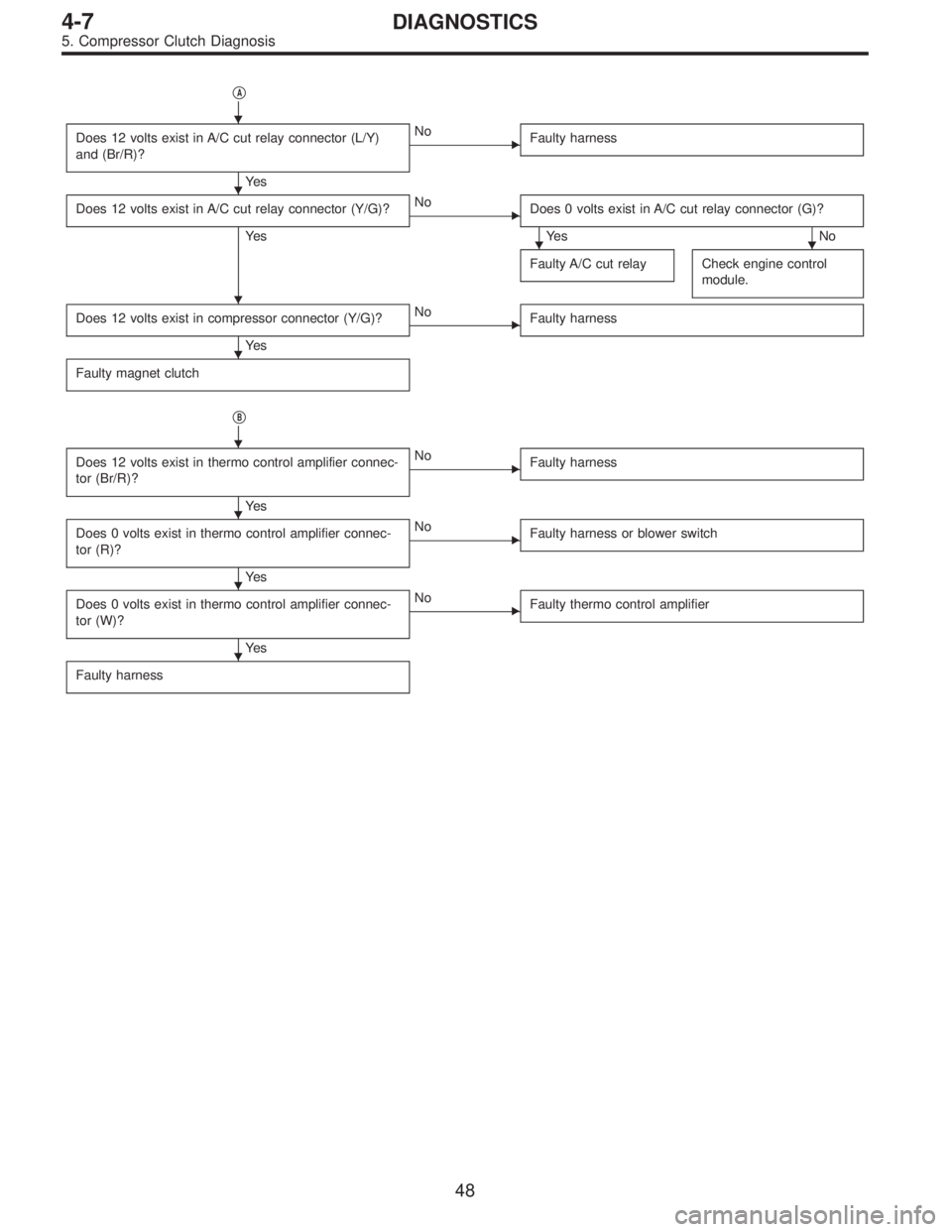
�A
Does 12 volts exist in A/C cut relay connector (L/Y)
and (Br/R)?
Ye s
�No
Faulty harness
Does 12 volts exist in A/C cut relay connector (Y/G)?
Ye s
�No
Does 0 volts exist in A/C cut relay connector (G)?
Ye s N o
Faulty A/C cut relay
Check engine control
module.
Does 12 volts exist in compressor connector (Y/G)?
Ye s
�No
Faulty harness
Faulty magnet clutch
�B
Does 12 volts exist in thermo control amplifier connec-
tor (Br/R)?
Ye s
�No
Faulty harness
Does 0 volts exist in thermo control amplifier connec-
tor (R)?
Ye s
�No
Faulty harness or blower switch
Does 0 volts exist in thermo control amplifier connec-
tor (W)?
Ye s
�No
Faulty thermo control amplifier
Faulty harness
�
�
��
�
�
�
�
�
�
48
4-7DIAGNOSTICS
5. Compressor Clutch Diagnosis
 Secure relay box connector to connector bracket.
CAUTION:
Align connector with mating receptacle.
3) Using cable clip, secure hydraulic unit harness to relay
box harness.
CAUTION:
Make sur")
 Secure relay box connector to connector bracket.
CAUTION:
Align connector with mating receptacle.
3) Using cable clip, secure hydraulic unit harness to relay
box harness.
CAUTION:
Make sur")

and fuse.
Does 12 volts exist")