Page 1727 of 2890
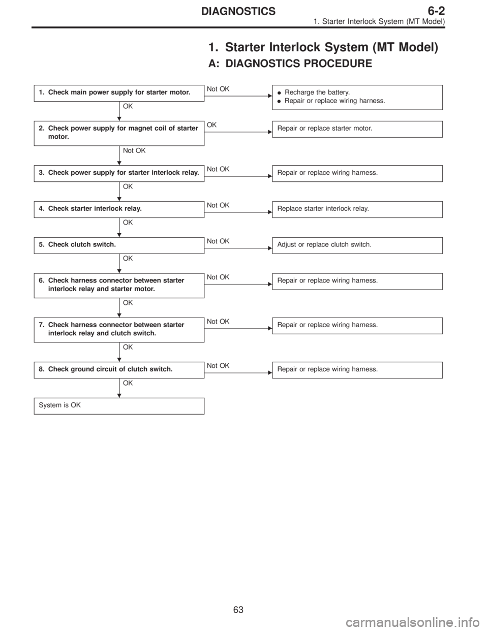
1. Starter Interlock System (MT Model)
A: DIAGNOSTICS PROCEDURE
1. Check main power supply for starter motor.
OK
�Not OK
�Recharge the battery.
�Repair or replace wiring harness.
2. Check power supply for magnet coil of starter
motor.
Not OK
�OK
Repair or replace starter motor.
3. Check power supply for starter interlock relay.
OK
�Not OK
Repair or replace wiring harness.
4. Check starter interlock relay.
OK
�Not OK
Replace starter interlock relay.
5. Check clutch switch.
OK
�Not OK
Adjust or replace clutch switch.
6. Check harness connector between starter
interlock relay and starter motor.
OK
�Not OK
Repair or replace wiring harness.
7. Check harness connector between starter
interlock relay and clutch switch.
OK
�Not OK
Repair or replace wiring harness.
8. Check ground circuit of clutch switch.
OK
�Not OK
Repair or replace wiring harness.
System is OK
�
�
�
�
�
�
�
�
63
6-2DIAGNOSTICS
1. Starter Interlock System (MT Model)
Page 1728 of 2890

B6M0383A
1. CHECK MAIN POWER SUPPLY FOR STARTER
MOTOR.
Measure voltage between starter motor terminal B and
body.
Connector & terminal / Specified voltage:
Terminal B—Body / 10 V, or more
B6M0384A
2. CHECK POWER SUPPLY FOR MAGNET COIL OF
STARTER MOTOR.
1) Disconnect all connectors from starter motor.
2) Turn ignition switch to ST (START).
3) Depress clutch pedal.
4) Measure voltage between starter motor terminal S con-
nector and body.
Connector & terminal / Specified voltage:
(B14) Terminal S—Body / 10 V, or more
B6M0385A
3. CHECK POWER SUPPLY FOR STARTER
INTERLOCK RELAY.
1) Disconnect all connectors from starter motor.
2) Disconnect connector of starter interlock relay.
3) Turn ignition switch to ST (START).
4) Measure voltage between starter interlock relay con-
nector and body.
Connector & terminal / Specified voltage:
(B105) No. 2—Body / 10 V, or more
(B105) No. 4—Body / 10 V, or more
B6M0386A
4. CHECK STARTER INTERLOCK RELAY.
1) Disconnect connector of starter interlock relay.
2) Connect battery to terminal No. 2 and ground terminal
No. 1.
3) Check continuity between terminals as indicated in
table below:
When current flows. Between terminals
No. 3 and No. 4Continuity exists.
When current does not flow. Between terminals
No. 3 and No. 4Continuity does not
exist.
Between terminals
No. 1 and No. 2Continuity exists.
64
6-2DIAGNOSTICS
1. Starter Interlock System (MT Model)
Page 1729 of 2890
 Disconnect connector of clutch switch.
2) Check continuity between terminals when clutch pedal
is depressed/released.
Terminals / Specified resistance:
No. 1—No.2/")
G6M0184
5. CHECK CLUTCH SWITCH.
1) Disconnect connector of clutch switch.
2) Check continuity between terminals when clutch pedal
is depressed/released.
Terminals / Specified resistance:
No. 1—No.2/10Ω, max.
(Without pedal depressing.)
/1MΩ, min. (Pedal depressing.)
B6M0387A
6. CHECK HARNESS CONNECTOR BETWEEN
STARTER INTERLOCK RELAY AND STARTER
MOTOR.
1) Disconnect connectors of starter interlock relay and
starter motor.
2) Measure resistance of harness connector between
starter interlock relay and starter motor.
Connector & terminal / Specified resistance:
(B105) No. 3—(B14) terminalS/10Ω, max.
B6M0388A
7. CHECK HARNESS CONNECTOR BETWEEN
STARTER INTERLOCK RELAY AND CLUTCH SWITCH.
1) Disconnect connectors of starter interlock relay and
clutch switch.
2) Measure resistance of harness connector between
starter interlock relay and clutch switch.
Connector & terminal / Specified resistance:
(B105) No. 1—(B106) No.2/10Ω, max.
B6M0389A
8. CHECK GROUND CIRCUIT OF CLUTCH SWITCH.
1) Disconnect connector of clutch switch.
2) Measure resistance of harness connector between
clutch switch and body.
Connector & terminal / Specified resistance:
(B106) No. 1—Body / 10Ω, max.
65
6-2DIAGNOSTICS
1. Starter Interlock System (MT Model)
Page 1739 of 2890

4. Power Window
A: DIAGNOSTICS PROCEDURE-1
Trouble symptom A: All door windows do not operate.
1. Check fuse and power supply.
OK
�Not OK
�Replace fuse or circuit breaker.
�Repair or replace wiring harness.
2. Check power window relay.
OK
�Not OK
Replace power window relay.
3. Check ground circuit of power window relay.
OK
�Not OK
Repair or replace wiring harness.
4. Check harness connector between power
window relay and power window main switch
(driver’s door switch).
OK
�Not OK
Repair or replace wiring harness.
5. Check power window main switch.
OK
�Not OK
Replace power window main switch.
6. Check ground circuit of power window main
switch.
OK
�Not OK
Repair or replace wiring harness.
System is OK.
B6M0390A
1. CHECK FUSE AND POWER SUPPLY.
1) Check fuse No. 15.
2) Disconnect connector of power window relay.
3) Turn ignition switch to ON.
4) Measure voltage between power window relay connec-
tor and body.
Connector & terminal / Specified voltage:
(B42) No. 1—Body / 10 V, or more
(B42) No. 2—Body / 10 V, or more
�
�
�
�
�
�
75
6-2DIAGNOSTICS
4. Power Window
Page 1740 of 2890
 Disconnect connector of power window relay.
2) Connect battery to terminal No. 1 and ground terminal
No. 3.
3) Check continuity between terminals as indicated")
B6M0391A
2. CHECK POWER WINDOW RELAY.
1) Disconnect connector of power window relay.
2) Connect battery to terminal No. 1 and ground terminal
No. 3.
3) Check continuity between terminals as indicated in
table below:
When current flows. Between terminals
No. 2 and No. 4Continuity exists.
When current does not flow. Between terminals
No. 2 and No. 4Continuity does not
exist.
Between terminals
No. 1 and No. 3Continuity exists.
B6M0392A
3. CHECK GROUND CIRCUIT OF POWER WINDOW
RELAY.
1) Disconnect connector of power window relay.
2) Measure resistance of harness connector between
power window relay and body.
Connector & terminal / Specified resistance:
(B42) No. 3—Body / 10Ω, max.
B6M0393A
4. CHECK HARNESS CONNECTOR BETWEEN
POWER WINDOW RELAY AND POWER WINDOW
MAIN SWITCH (DRIVER’S DOOR SWITCH).
1) Disconnect connectors of power window relay and
power window main switch.
2) Measure resistance of harness connector between
power window relay and power window main switch.
Connector & terminal / Specified resistance:
(B42) No. 4—(D7) No.7/10Ω, max.
5. CHECK POWER WINDOW MAIN SWITCH.
Refer to 6-2 [W16B1] for inspection of power window main
switch.
76
6-2DIAGNOSTICS
4. Power Window
Page 1749 of 2890
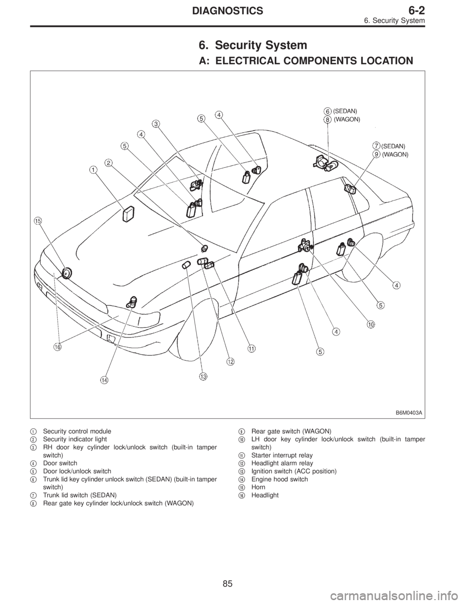
6. Security System
A: ELECTRICAL COMPONENTS LOCATION
B6M0403A
�1Security control module
�
2Security indicator light
�
3RH door key cylinder lock/unlock switch (built-in tamper
switch)
�
4Door switch
�
5Door lock/unlock switch
�
6Trunk lid key cylinder unlock switch (SEDAN) (built-in tamper
switch)
�
7Trunk lid switch (SEDAN)
�
8Rear gate key cylinder lock/unlock switch (WAGON)�
9Rear gate switch (WAGON)
�
10LH door key cylinder lock/unlock switch (built-in tamper
switch)
�
11Starter interrupt relay
�
12Headlight alarm relay
�
13Ignition switch (ACC position)
�
14Engine hood switch
�
15Horn
�
16Headlight
85
6-2DIAGNOSTICS
6. Security System
Page 1751 of 2890

Door lock/unlock switch1
(INPUT)�Battery voltage is present when all doors")
C: CONTROL MODULE I/O SIGNAL
B6M0405
Content Terminal No.Measuring conditions and I/O signals
(Ignition switch ACC position)
Door lock/unlock switch1
(INPUT)�Battery voltage is present when all doors and rear gate (WAGON) are locked.
�“0”volt is present when one of the doors or rear gate (WAGON) is unlocked.
Key cylinder lock switch2
(INPUT)�“0”volt is present when key cylinder is turned to LOCK position.
�Battery voltage is present when key cylinder is in positions other than LOCK.
Tamper switch3
(INPUT)�Battery voltage is present when key cylinder switch is installed to key cylinder.
�“0”volt is present when key cylinder switch is removed from key cylinder.
Door switch4
(INPUT)�Battery voltage is present when all doors are closed.
�“0”volt is present when one of the doors is open.
Starter interrupt relay5
(OUTPUT)�Battery voltage is present when ignition switch is turned ACC or ON.
�“0”volt is present when security system is in alarm state.
Ignition switch (ACC)6
(INPUT)�Battery voltage is present when ignition switch is turned ACC or ON.
�“0”volt is present when ignition switch is turned OFF.
Security indicator light7
(OUTPUT)�Battery voltage is present when indicator light goes off.
�“0”volt is present when indicator light illuminates.
Power supply (back-up) 8 Battery voltage is constantly present.
Ground 9—
Engine hood switch10
(INPUT)�Battery voltage is present when engine hood is closed.
�“0”volt is present when engine hood is open.
Trunk lid switch (SEDAN)
Rear gate switch (WAGON)11
(INPUT)�Battery voltage is present when trunk lid or rear gate is closed.
�“0”volt is present when trunk lid or rear gate is open.
Headlight alarm relay12
(OUTPUT)�Battery voltage is present when ignition switch is turned ACC or ON.
�“0”volt and battery voltage repeats in alarm state. (Headlights flash intermittently
at 0.2 sec. ON and 0.6 sec. OFF intervals).
Horn relay13
(OUTPUT)�Battery voltage is present when ignition switch is turned ACC or ON.
�“0”volt and battery voltage repeats in alarm state. (Horn sounds intermittently at
0.2 sec. ON and 0.6 sec. OFF intervals.)
Key cylinder unlock switch14
(INPUT)�“0”volt is present when key cylinder is turned to UNLOCK position.
�Battery voltage is present when key cylinder is in positions other than UNLOCK.
Trunk lid key cylinder unlock
switch (SEDAN)15
(INPUT)�“0”volt is present when trunk lid key cylinder is turned to UNLOCK position.
�Battery voltage is present when trunk lid key cylinder is in positions other than
UNLOCK.
87
6-2DIAGNOSTICS
6. Security System
Page 1752 of 2890

D: BASIC DIAGNOSTICS PROCEDURE
Start security system check.
Fully open all door windows and turn ignition switch OFF.
Take key out of ignition, exit vehicle and lock driver’s door.
Indicator light illuminates.
OK The light flashes.
� The light does not
illuminate.
Check indicator harness.
Check security indicator light.
Check driver’s door key cylinder lock/unlock switch.
Check security control module.
Check whether switch input signal remains UNLOCK.
Check wiring harness.
Check switch input signals.
(Harnesses and switches separately)
(Tamper, door, hood, trunk and rear gate
switch)Check security control module.
Wait for 30 seconds.
Indicator light flashes at long intervals (0.2 sec. ON and 2.4 sec.
OFF).
OK
� Not OK
Check security control module.
Unlock driver’s door using the inside lock knob and open door.
The horn sounds and headlights flash intermittently at 0.2 sec. ON
and 0.6 sec. OFF intervals.
The engine will not start even if the ignition switch is turned to
START. Indicator lamp goes out.
OK Starter motor runs.
� All are not OK.
Check driver’s door switch.
Check wiring harness.
Check security control module.
� Horn is not OK.
Check horn
operation by
pushing horn pad
on steering wheel.
OK
� Not OK
Check horn.
Check horn relay.
Check security control module.
Check harness between horn relay and security control module.
� Headlights are not
OK.
Check headlights
operation by
turning light switch
ON/OFF.
OK
� Not OK
Check headlight
bulbs.
Check combination
switch.
Check headlight
relay.
Check starter interrupt relay.
Check wiring harness.
Check security control module.Check headlight alarm relay.
Check security control module.
Check wiring harness.
The alarm system continues to operate for 150 seconds.
OK Not OK
The horn and
headlights turn off.
The starter motor
does not run.
OK
� Not OK
Check security
control module.
Unlock the driver’s door using ignition key.
Continues to next step.
�
�
�
�
�
�
�
�
�
��
�
��
�
�
88
6-2DIAGNOSTICS
6. Security System