Page 912 of 2890

No. Part name Wire dia. Outer dia. Effective turn Free length
25 Pressure regulator spring 1.6 (0.063) 14.0 (0.551) 5.6 31.5 (1.240)
26 Pressure modifier spring 0.8 (0.031) 6.8 (0.268) 1")
Unit: mm (in)
No. Part name Wire dia. Outer dia. Effective turn Free length
25 Pressure regulator spring 1.6 (0.063) 14.0 (0.551) 5.6 31.5 (1.240)
26 Pressure modifier spring 0.8 (0.031) 6.8 (0.268) 10.0 31.95 (1.2579)
27 Modifier accumulator spring 1.3 (0.051) 9.8 (0.386) 8.8 30.5 (1.201)
28 Pilot spring 1.1 (0.043) 9.1 (0.358) 8.3 25.7 (1.012)
29 Accumulator control spring 0.4 (0.016) 6.6 (0.260) 11.0 27.5 (1.083)
30 Shift B spring 0.65 (0.0256) 7.0 (0.276) 9.5 25.0 (0.984)
31 Shift A spring 0.5 (0.020) 7.0 (0.276) 9.5 25.0 (0.984)
32 Shuttle shift spring 0.65 (0.0256) 5.65 (0.2224) 27.6 51.0 (2.008)
33 Overrunning clutch control spring 0.7 (0.028) 6.0 (0.236) 12.0 26.5 (1.043)
34 4-2 sequence spring 0.55 (0.0217) 6.95 (0.2736) 11.0 29.1 (1.146)
35 4-2 relay spring 0.55 (0.0217) 6.95 (0.2736) 11.0 29.1 (1.146)
36 Servo charger spring 0.7 (0.028) 6.7 (0.264) 9.0 23.0 (0.906)
37 3-2 timing spring 0.75 (0.0295) 6.75 (0.2657) 7.5 20.55 (0.8091)
38 1st reducing spring 0.75 (0.0295) 6.75 (0.2657) 12.5 25.4 (1.000)
39 Overrunning clutch reducing spring 1.05 (0.0413) 7.05 (0.2776) 15.21 34.7 (1.366)
40 Torque converter regulator spring 1.3 (0.051) 9.0 (0.354) 11.7 38.0 (1.496)
41 Lock-up control spring 0.75 (0.0295) 13.0 (0.512) 3.5 18.5 (0.728)
42 Shuttle duty shift spring 0.75 (0.0295) 5.65 (0.2224) 27.6 51.0 (2.008)
86
3-2SERVICE PROCEDURE
6. Control Valve Body
Page 1222 of 2890
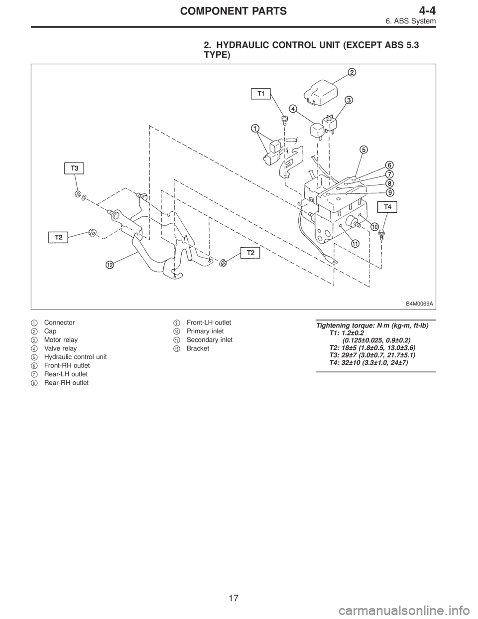
2. HYDRAULIC CONTROL UNIT (EXCEPT ABS 5.3
TYPE)
B4M0069A
�1Connector
�
2Cap
�
3Motor relay
�
4Valve relay
�
5Hydraulic control unit
�
6Front-RH outlet
�
7Rear-LH outlet
�
8Rear-RH outlet�
9Front-LH outlet
�
10Primary inlet
�
11Secondary inlet
�
12Bracket
Tightening torque: N⋅m (kg-m, ft-lb)
T1: 1.2±0.2
(0.125±0.025, 0.9±0.2)
T2: 18±5 (1.8±0.5, 13.0±3.6)
T3: 29±7 (3.0±0.7, 21.7±5.1)
T4: 32±10 (3.3±1.0, 24±7)
17
4-4COMPONENT PARTS
6. ABS System
Page 1224 of 2890
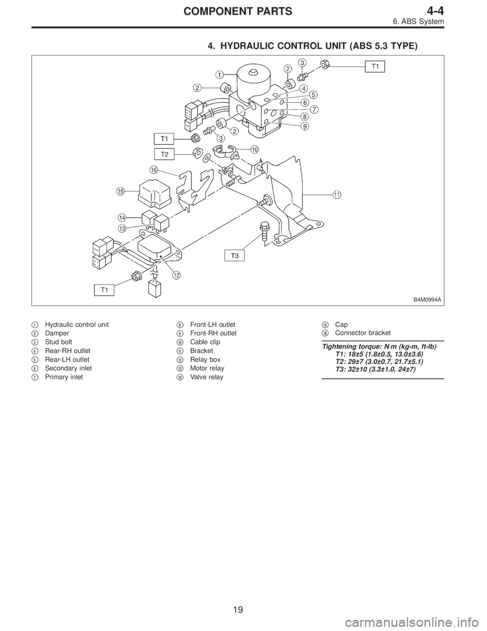
4. HYDRAULIC CONTROL UNIT (ABS 5.3 TYPE)
B4M0994A
�1Hydraulic control unit
�
2Damper
�
3Stud bolt
�
4Rear-RH outlet
�
5Rear-LH outlet
�
6Secondary inlet
�
7Primary inlet�
8Front-LH outlet
�
9Front-RH outlet
�
10Cable clip
�
11Bracket
�
12Relay box
�
13Motor relay
�
14Valve relay�
15Cap
�
16Connector bracket
Tightening torque: N⋅m (kg-m, ft-lb)
T1: 18±5 (1.8±0.5, 13.0±3.6)
T2: 29±7 (3.0±0.7, 21.7±5.1)
T3: 32±10 (3.3±1.0, 24±7)
19
4-4COMPONENT PARTS
6. ABS System
Page 1228 of 2890
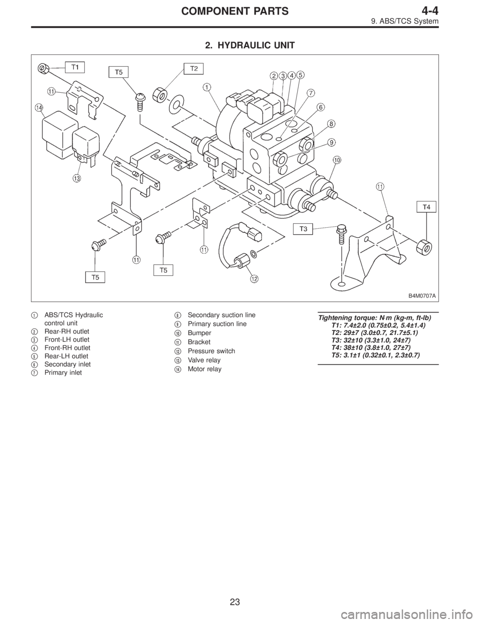
2. HYDRAULIC UNIT
B4M0707A
�1ABS/TCS Hydraulic
control unit
�
2Rear-RH outlet
�
3Front-LH outlet
�
4Front-RH outlet
�
5Rear-LH outlet
�
6Secondary inlet
�
7Primary inlet�
8Secondary suction line
�
9Primary suction line
�
10Bumper
�
11Bracket
�
12Pressure switch
�
13Valve relay
�
14Motor relay
Tightening torque: N⋅m (kg-m, ft-lb)
T1: 7.4±2.0 (0.75±0.2, 5.4±1.4)
T2: 29±7 (3.0±0.7, 21.7±5.1)
T3: 32±10 (3.3±1.0, 24±7)
T4: 38±10 (3.8±1.0, 27±7)
T5: 3.1±1 (0.32±0.1, 2.3±0.7)
23
4-4COMPONENT PARTS
9. ABS/TCS System
Page 1280 of 2890

B4M0069A
�1Connector
�
2Cap
�
3Motor relay
�
4Valve relay
�
5Hydraulic control unit
�
6Front-RH outlet
�
7Rear-LH outlet�
8Rear-RH outlet
�
9Fro")
15. Hydraulic Unit for ABS System
(Except ABS 5.3 Type)
B4M0069A
�1Connector
�
2Cap
�
3Motor relay
�
4Valve relay
�
5Hydraulic control unit
�
6Front-RH outlet
�
7Rear-LH outlet�
8Rear-RH outlet
�
9Front-LH outlet
�
10Primary inlet
�
11Secondary inlet
�
12Bracket
Tightening torque: N⋅m (kg-m, ft-lb)
T1: 1.2±0.2
(0.125±0.025, 0.9±0.2)
T2: 18±5 (1.8±0.5, 13.0±3.6)
T3: 29±7 (3.0±0.7, 21.7±5.1)
T4: 32±10 (3.3±1.0, 24±7)
A: REMOVAL
1) Remove air intake duct.
2) Remove canister from engine compartment to facilitate
removal of hydraulic unit.
3) Disconnect brake pipes from hydraulic unit and plug
open joints to prevent entry of foreign particles.
G4M0455
4) Remove nuts and bolts which secure hydraulic unit, and
remove hydraulic unit from engine compartment.
CAUTION:
�Hydraulic unit cannot be disassembled. Do not
attempt to loosen bolts and nuts.
�Do not drop or bump hydraulic unit.
�Do not turn the hydraulic unit upside down or place
it on its side.
73
4-4SERVICE PROCEDURE
15. Hydraulic Unit for ABS System (Except ABS 5.3 Type)
Page 1281 of 2890
�Be careful to prevent foreign particles from getting into
hydraulic unit.
�When a new hydraulic unit is installed, apply a coat of
rust-preventive wax (Nippeco LT or GB) to bracket attach-
ing bolts after tightening.
�Do not pull harness disconnecting harness connector.
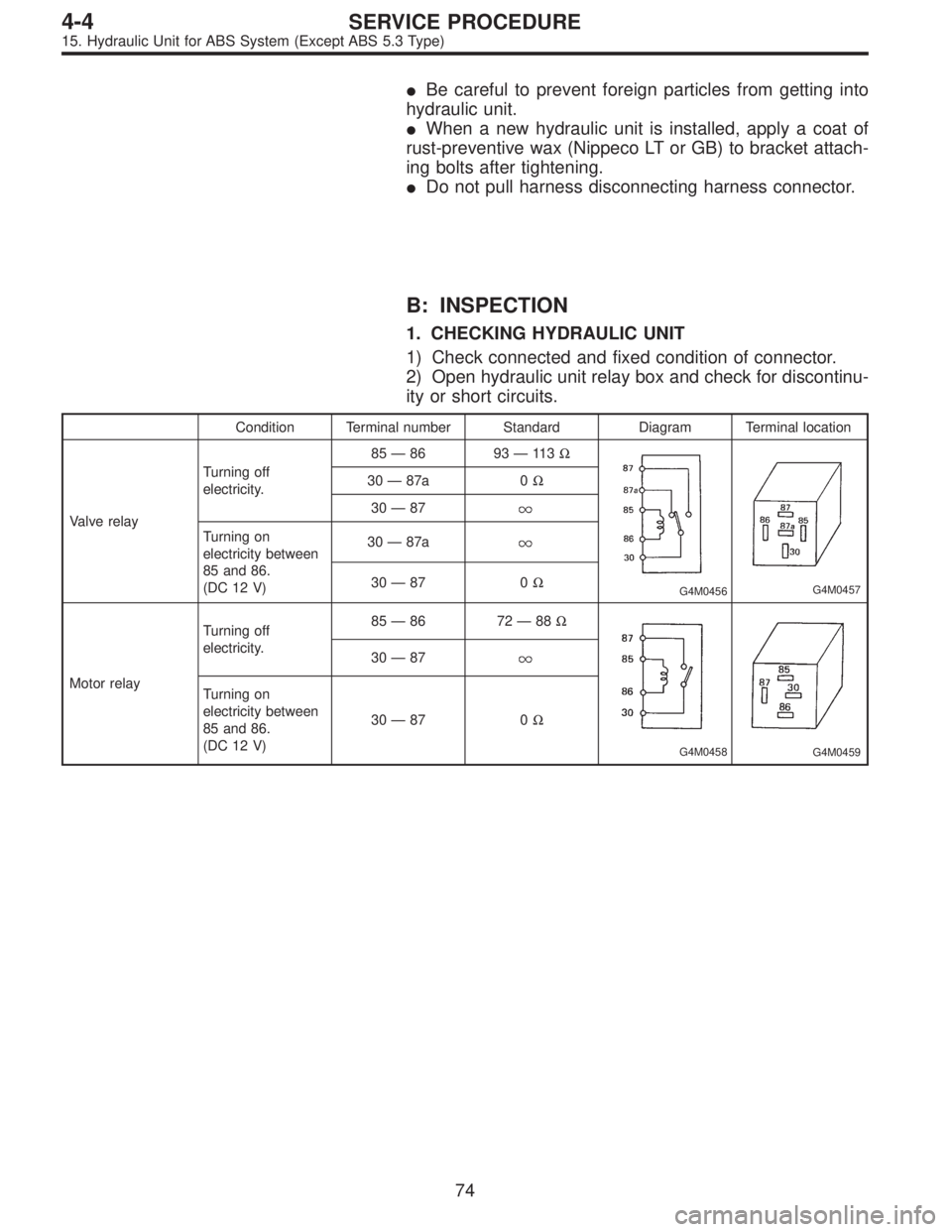
B: INSPECTION
1. CHECKING HYDRAULIC UNIT
1) Check connected and fixed condition of connector.
2) Open hydraulic unit relay box and check for discontinu-
ity or short circuits.
Condition Terminal number Standard Diagram Terminal location
Valve relayTurning off
electricity.85—86 93—11 3Ω
G4M0456G4M0457
30—87a 0Ω
30—87
Turning on
electricity between
85 and 86.
(DC 12 V)30—87a
30—87 0Ω
Motor relayTurning off
electricity.85—86 72—88Ω
G4M0458G4M0459
30—87
Turning on
electricity between
85 and 86.
(DC 12 V)30—87 0Ω
74
4-4SERVICE PROCEDURE
15. Hydraulic Unit for ABS System (Except ABS 5.3 Type)
Page 1287 of 2890
G4M0455
D: INSTALLATION
1) Install relay box cover on hydraulic unit.
2) Install hydraulic unit to bracket.
Tightening torque:
18±5 N⋅m (1.8±0.5 kg-m, 13.0±3.6 ft-lb)
3) Tighten bracket and motor ground lead as a unit.
Tightening torque:
32±10 N⋅m (3.3±1.0 kg-m, 24±7 ft-lb)
4) Connect brake pipes to their correct hydraulic unit con-
nections.
Tightening torque:
15
+3
�2N⋅m (1.5+0.3
�0.2kg-m, 10.8+2.2
�1.4ft-lb)
16. ABS Control Module (Except ABS
5.3 Type)
A: REMOVAL
1) Remove floor mat located under lower right side of front
seat.
G4M0468
2) Remove screw which secure ABS control module from
the body.
G4M0469
3) Disconnect connector from ABS control module.
80
4-4SERVICE PROCEDURE
15. Hydraulic Unit for ABS System (Except ABS 5.3 Type) - 16. ABS Control Module (Except ABS 5.3 Type)
Page 1288 of 2890
G4M0455
D: INSTALLATION
1) Install relay box cover on hydraulic unit.
2) Install hydraulic unit to bracket.
Tightening torque:
18±5 N⋅m (1.8±0.5 kg-m, 13.0±3.6 ft-lb)
3) Tighten bracket and motor ground lead as a unit.
Tightening torque:
32±10 N⋅m (3.3±1.0 kg-m, 24±7 ft-lb)
4) Connect brake pipes to their correct hydraulic unit con-
nections.
Tightening torque:
15
+3
�2N⋅m (1.5+0.3
�0.2kg-m, 10.8+2.2
�1.4ft-lb)
16. ABS Control Module (Except ABS
5.3 Type)
A: REMOVAL
1) Remove floor mat located under lower right side of front
seat.
G4M0468
2) Remove screw which secure ABS control module from
the body.
G4M0469
3) Disconnect connector from ABS control module.
80
4-4SERVICE PROCEDURE
15. Hydraulic Unit for ABS System (Except ABS 5.3 Type) - 16. ABS Control Module (Except ABS 5.3 Type)
 Install relay box cover on hydraulic unit.
2) Install hydraulic unit to bracket.
Tightening torque:
18±5 N⋅m (1.8±0.5 kg-m, 13.0±3.6 ft-lb)
3) Tighten bracket and motor")
 Install relay box cover on hydraulic unit.
2) Install hydraulic unit to bracket.
Tightening torque:
18±5 N⋅m (1.8±0.5 kg-m, 13.0±3.6 ft-lb)
3) Tighten bracket and motor")