Page 253 of 2890
2_7
[T1oBUS1
ON-BOARD
DIAGNOSTICS
II
SYSTEM
10
.
Diagnostics
Chart
with
Trouble
Code
R68
B2M0932A
I
10BU5
I
PRESSURE
CONTROL
SOLENOID
VALVE
.
1)
Turn
ignition
switch
to
ON
.
2)
Measure
voltage
between
fuel
tankpressure
control
solenoid
valve
and
chassis
ground
.
CHECK
:
Connector
&
terminal
(R68)
No
.
1
(+)
-
Chassis
ground
(
)
:
Is
the
voltage
more
than
10
V?
,res
:
Go
tonext
CHECK
o
:
Repair
harness
and
connector
.
NOTE
:
In
this
case,
repair
the
following
:
9
Open
circuit
in
harness
between
main
relay
and
fuel
tankpressure
control
solenoid
valve
connector
"
Poor
contact
in
coupling
connectors
(B97
and
R57)
"
Poor
contact
in
main
relay
connector
CHECK
:
Is
there
poor
contact
in
fuel
tank
pressure
control
solenoid
valve
connector?
,res
:
Repair
poor
contact
in
fuel
tank
pressure
control
solenoid
valve
connector
.
No
:
Contact
with
SOA
service
.
NOTE
:
Inspection
by
DTM
is
required,
because
probable
cause
is
deterioration
of
multiple
parts
.
42
Page 254 of 2890
2-7
[T1
oBVO1
ON-BOARD
DIAGNOSTICS
II
SYSTEM
10
.
Diagnostics
Chart
with
Trouble
Code
OBD
(FBI)
P1401
H21
M1410
BV
:
DTC
P1401
-
FUEL
TANK
PRESSURE
CONTROL
SYSTEM
FUNCTION
PROBLEM
(PCV
-
F)
-
DTC
DETECTING
CONDITION
:
Two
consecutive
trips
with
fault
10BV1
Check
fuel
tank
pressure
control
solenoid
valve
.
CAUTION
:
After
repair
or
replacement
of
faulty
parts,
conduct
CLEAR
MEMORY
and
INSPECTION
MODES
.
<
Ref
.
to
2-7
[T3D0]
and
[T3E0]
.*2
and
*4
>
WIRING
DIAGRAM
:
Main
relay
0
0
01F
B47861F45
SBF-2
B84
E
E)E)
ECM
ra
Ti
S
.M
.J
.
891
Rt
R15
R57R68
Fuel
tankpressure
control
solenoid
valve
847
R57R68
10
U
1112
U
131401
16
1
131
1
4041424344
1
2
960
6162
63
64
6
-769
69
70
34
1~,~y(3~
8
.04
687
8
99091929
949
96
6
14j5jti1/LtiJ
B2M1020
44
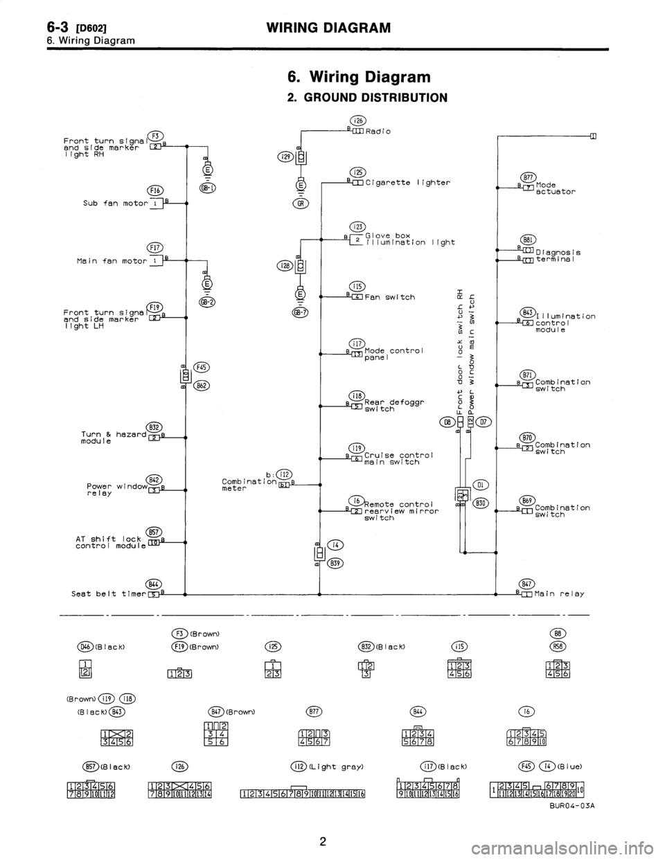
Page 267 of 2890

6-3
IDso21
WIRING
DIAGRAM
6
.
Wiring
Diagram
6
.
Wiring
Diagram
2
.
GROUND
DISTRIBUTION
i26
Radio
Front
turn
signal
F3
and
sidemarker
z
light
RH
Cigarette
lighter
8~7
Mode
Flb
~
actuator
Subfan
motor
i
GR
f17
Main
fan
motor
11
Front
turn
signs
F~
and
sidemarker
light
LH
Turn
&
hazard
B32
module
Power
wind
relay
AT
shift
lock
control
module
B64
Seat
belt
timer[5
:ji
D66
Bleck>
2
(Brown)
i19
i1B
(B
I
e
C
K)
843
1
2
3456
B57
(g
I
ac
k)
123456
71319461111121
13
'D
2
box
iiio1vuemination
light
=
0
1
agnos
1
a
---B=
term
!
na
I
CD
E
T
B
Fan
switch
GB-7
L
+~
~
3
(9)Illumination
control
module
i
17
s
Mode
control
a
panel
-
om
FGS
L
O
oc
~
B71
3
e
Comb
i
nat
i
on
i18
C~'
sw
i
tch
Rear
defoggro0
switch
870
e
Combination
a
Cruise
control`-'switch
main
switch
b
:
i12
Combination
meter
emote
control
~
830
Combination
rearview
mirror
,
,switch
"J
switch
m
B39
B47
Mainrela
y
(B
r
own>
(B
r
own)
(~D(B
I
ack)
F1721
123
F1
f2T3-1
F1
r2
M
G31
M-
4
MS6
141516
(~~
(Brown)
(D
j
24
3
q
S6
1
23
F45T6
7
1
234
S678
PM
1
2
30
78
CD
(~D(Light
gray)
ill
Bleck>
F45
i4
(Blue)
123
456
12345678
234
6789
1
~~
7891011121314
12345678910111213141516
910111213141516
11
(21314151617181920
BUR04-03A
2
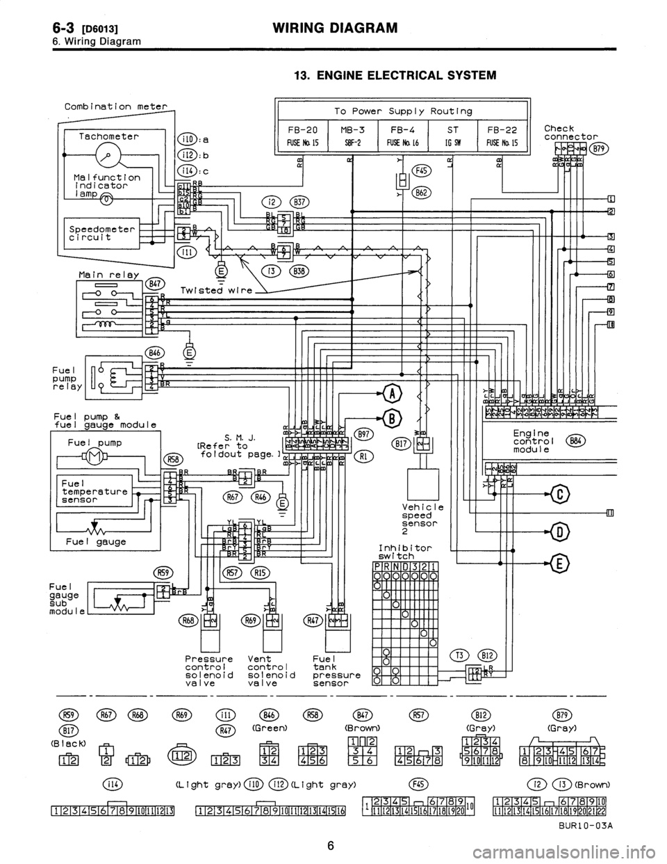
Page 270 of 2890

6-3
IDso1a1
WIRING
DIAGRAM
6
.
Wiring
Diagram
R57R15
Combination
meter
To
Power
Supply
Routing
FB-20
MB-3FB-4
ST
FB-22Check
Tachometer
connector
FUSE
Na
15
S8F-2
FUSE
Na
16
[G
519
FUSE
Na
l5
P
v
1-0
B79
CD
:
bm
rI
a
m
~
~
F45
Malfunction
Q
D
:
C
indicator
,
.
862
lamp
7
Speedometer
B
i
circuit
I11
*c~
)
Main
relay
E
o
B47
=
Twisted
wire
=2
R
0
F-0
0-
<
71
846
E
Fuel
pump
relay
"
>-
3z
M
~`
LL
J
C
A
V
mJ
(7
Fue
I
pump
&
~
MM~mVPPP
-+
fuel
gauge
module
~
Jv
Fue
I
S
.
M
.
J
.
mJ
B97
3
Engine
pump
[Refer'
to
a
1,
B17
control
B84
module
foldout
page
.],
JJ
Rl
~/
m
L
C
O
R
Fuel
ix
J
temperature
R67R46
sensor
u
Vehicle
=
speed
'
rr
sensor
D
Fuel
gauge
~
r
Inhibitor
switch
n
R59
Fue
I
gauge
C~
sub
module
R59
R67R68
B17
(B
lack)
12
2
12
C
i14
111213141516171819110111112113
((
9
)
5
1
F1F1
Pressure
Vent
controlcontrol
solenoid
solenoi
valvevalve
R69
OD
846
R47
(Green)
U
:Z~)
123
~
34
13
.
ENGINE
ELECTRICAL
SYSTEM
R47
F-1
Fuel
tank
d
pressure
sensor
(Brown)
M
F1F2-1
'
2
3
[3141
456
1516
(L
I
ght
gray)
i
10
(
2D
(L
i
ght
gray)
12345678910111213(41516
B12
R57B12
(Gray)
1234
12
3
5678
45678
9101112
F45
B79
(Gray)
1
23
45
67
89
IO
1t
12
1314
(2i3
(Brown)
23456789
12345
678910
1111213141516171819201
[t
1
1
12
1
13
1
14
1
15
1
16
1
17
1
18
1
19
1
20
21
1
99
1
BUR10-03A
6
Page 277 of 2890
Connector
Connecting
to
No
.
Pole
Color
Area
No
.
Name
R22
1
Brown
C-1
Rear
door
switch
LH
R23
6
G2
Power
antenna
R25
2
Black
C-3
Rear
defogger
condenser
R26
4
Black
D-4
Rear
combination
light
RH
R28
4
Black
C-2
Rear
combination
light
LH
R36
5
Black
C-3
Rear
wiper
relay
R37
2
C-3
D33
R38
4
G3
D34
Rear
gatecord
R39
8
C-4
D35
R47
3
I
D-3
I
Fuel
tank
pressure
sensor
Connector
Connecting
to
No
.
Pole
Color
Area
No
.
Name
D33
2
C-3
R37
D34
4C-3
R38
Rear
wiring
harness
D35
8
C-4
R39
D37
1
Black
B-3L
li
D38
1
B-3
uggage
room
ght
D39
2B-3
High-mounted
stop
light
D40
1
Black
B-4
Rear
defogger
(Power)
D42
4B-4
Rear
finisher
light
RH
D43
48-3
Rear
wiper
motor
D44
2B-4
License
plate
light
RH
D45
2A-3
License
plate
light
LH
D46
2
Black
A-4
Rear
gate
latch
switch
D47
4
A-4
Rear
gate
lock
actuator
D48
1
Black
B-3
Rear
defogger
(Ground)
D49
I
4A-3
Rear
finisher
light
LH
''
Non-colored
9
.
REAR
END
WIRING
HARNESS
AND
GROUND
POINT
1
243
B
C
C
D
B6M069
1
2
3_
I
4
13
11`~~Il'//
Page 278 of 2890
Connector
Connecting
to
No
.
Pole
Color
Area
No
.
Name
R22
1
Brown
C-1
Rear
door
switch
LH
R23
6
G2
Power
antenna
R25
2
Black
C-3
Rear
defogger
condenser
R26
4
Black
D-4
Rear
combination
light
RH
R28
4
Black
C-2
Rear
combination
light
LH
R36
5
Black
C-3
Rear
wiper
relay
R37
2
C-3
D33
R38
4
G3
D34
Rear
gatecord
R39
8
C-4
D35
R47
3
I
D-3
I
Fuel
tank
pressure
sensor
Connector
Connecting
to
No
.
Pole
Color
Area
No
.
Name
D33
2
C-3
R37
D34
4C-3
R38
Rear
wiring
harness
D35
8
C-4
R39
D37
1
Black
B-3L
li
D38
1
B-3
uggage
room
ght
D39
2B-3
High-mounted
stop
light
D40
1
Black
B-4
Rear
defogger
(Power)
D42
4B-4
Rear
finisher
light
RH
D43
48-3
Rear
wiper
motor
D44
2B-4
License
plate
light
RH
D45
2A-3
License
plate
light
LH
D46
2
Black
A-4
Rear
gate
latch
switch
D47
4
A-4
Rear
gate
lock
actuator
D48
1
Black
B-3
Rear
defogger
(Ground)
D49
I
4A-3
Rear
finisher
light
LH
''
Non-colored
9
.
REAR
END
WIRING
HARNESS
AND
GROUND
POINT
1
243
B
C
C
D
B6M069
1
2
3_
I
4
13
11`~~Il'//
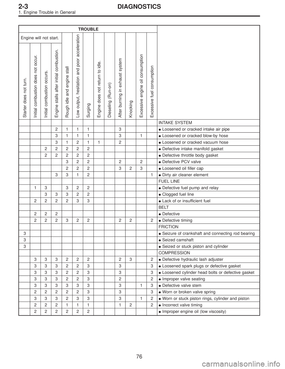
Page 386 of 2890

TROUBLE
Engine will not start.
Rough idle and engine stall
Low output, hesitation and poor acceleration
Surging
Engine does not return to idle.
Dieseling (Run-on)
After burning in exhaust system
Knocking
Excessive engine oil consumption
Excessive fuel consumption Starter does not turn.
Initial combustion does not occur.
Initial combustion occurs.
Engine stalls after initial combustion.
INTAKE SYSTEM
2111 3�Loosened or cracked intake air pipe
3111 3 1�Loosened or cracked blow-by hose
31211 2�Loosened or cracked vacuum hose
22222�Defective intake manifold gasket
22222�Defective throttle body gasket
322 2 2�Defective PCV valve
222 323�Loosened oil filler cap
3312 1�Dirty air cleaner element
FUEL LINE
13 322�Defective fuel pump and relay
33322�Clogged fuel line
222233�Lack of or insufficient fuel
BELT
222�Defective
222322 22 2�Defective timing
FRICTION
3�Seizure of crankshaft and connecting rod bearing
3�Seized camshaft
3�Seized or stuck piston and cylinder
COMPRESSION
333222 23 2�Defective hydraulic lash adjuster
333223 3 3�Loosened spark plugs or defective gasket
333223 3 3�Loosened cylinder head bolts or defective gasket
333223 2 2�Improper valve seating
333333 3 13�Defective valve stem
222223 3 3�Worn or broken valve spring
333233 3 12�Worn or stuck piston rings, cylinder and piston
222111 12 2�Incorrect valve timing
222222�Improper engine oil (low viscosity)
76
2-3DIAGNOSTICS
1. Engine Trouble in General
Page 464 of 2890

TROUBLE
Engine will not start.
Rough idle and engine stall
Low output, hesitation and poor acceleration
Surging
Engine does not return to idle.
Dieseling (Run-on)
After burning in exhaust system
Knocking
Excessive engine oil consumption
Excessive fuel consumption Starter does not turn.
Initial combustion does not occur.
Initial combustion occurs.
Engine stalls after initial combustion.
INTAKE SYSTEM
2111 3�Loosened or cracked intake air pipe
3111 3 1�Loosened or cracked blow-by hose
31211 2�Loosened or cracked vacuum hose
22222�Defective intake manifold gasket
22222�Defective throttle body gasket
322 2 2�Defective PCV valve
222 323�Loosened oil filler cap
3312 1�Dirty air cleaner element
FUEL LINE
13 322�Defective fuel pump and relay
33322�Clogged fuel line
222233�Lack of or insufficient fuel
BELT
222�Defective
222322 22 2�Defective timing
FRICTION
3�Seizure of crankshaft and connecting rod bearing
3�Seized camshaft
3�Seized or stuck piston and cylinder
COMPRESSION
333222 23 2�Defective hydraulic lash adjuster
333223 3 3�Loosened spark plugs or defective gasket
333223 3 3�Loosened cylinder head bolts or defective gasket
333223 2 2�Improper valve seating
333333 3 13�Defective valve stem
222223 3 3�Worn or broken valve spring
333233 3 12�Worn or stuck piston rings, cylinder and piston
222111 12 2�Incorrect valve timing
222222�Improper engine oil (low viscosity)
76
2-3bDIAGNOSTICS
1. Engine Trouble in General