Page 175 of 2890
![SUBARU LEGACY 1996 Service Repair Manual
s-$
[D601]
WIRING
DIAGRAM
6
.
Wiring
Diagram
No
.
Load
MB-2
Powerwindow
circuit
breaker
Engine
control
module
Fuel
pump
relay
MB-3
Main
relay
OBD-II
service
connector
MB-4A/C
relay
holder
MB- SUBARU LEGACY 1996 Service Repair Manual
s-$
[D601]
WIRING
DIAGRAM
6
.
Wiring
Diagram
No
.
Load
MB-2
Powerwindow
circuit
breaker
Engine
control
module
Fuel
pump
relay
MB-3
Main
relay
OBD-II
service
connector
MB-4A/C
relay
holder
MB-](/manual-img/17/57433/w960_57433-174.png)
s-$
[D601]
WIRING
DIAGRAM
6
.
Wiring
Diagram
No
.
Load
MB-2
Powerwindow
circuit
breaker
Engine
control
module
Fuel
pump
relay
MB-3
Main
relay
OBD-II
service
connector
MB-4A/C
relay
holder
MB-6
Headlight
LH
Diode
(Lighting)
Lighting
switch
Combination
meter
M
B_$
Headlight
RH
Combination
meter
Door
lock
timer
MB-9
Luggage
room
light
Radio
Room
light
MB-10
A/C
relay
holder
ALT-1
Combination
meter
IG
A/C
relay
holder
Cruise
control
module
ST
Engine
control
module
Inhibitor
switch
FB-2
Diode
(A/C)
Sub
fan
motor
FB-3
Sub
fan
relay-2
Engine
control
module
Fuel
pump
relay
FB-4
Ignition
coil
Transmission
control
module
Side
marker
light
LH
FB-6
Side
marker
light
RH
FB-7Door
lock
timer
FB-9Hazard
switch
AT
shift
lock
control
module
FB-10
Key
warning
switch
Power
antenna
FB-11
Radio
FB-12
Cigarette
lighter
FB-13
Remote
control
rearview
mirrorswitch
AT
shift
lock
control
module
Combination
switch
Front
washer
motor
FB-14
Front
wipermotor
Rear
washer
motor
Rear
wipermotor
Rear
wiper
relay
FB-15Transmission
control
module
Na
Load
Rear
defogger
FB-16
Rear
defogger
condenser
Reardefogger
switch
FB-17
Rear
defogger
switch
FB-18
AT
shift
lock
control
module
Inhibitor
switch
FB-19
Hazard
switch
Combination
meter
FB-20
Mode
control
panel
FB-21
Combination
meter
(Airbag)
Blower
motor
relay
Check
connector
FB-22
FRESH/RECIRC
actuator
Mode
actuator
Powerwindow
relay
Seat
belt
timer
FB-23
Airbag
.
control
module
FB-24
Airbag
control
module
FB-25
Lighting
switch
FB-26
Parking
switch
FB-27
Parking
switch
FB-28
Illumination
light
FB-29
Illumination
light
FB-30
Stop
light
switch
Stop
&
brake
switch
FB-31
Horn
relay
FB-32
Blower
motor
relay
FB-33
Parking
switch
License
plate
light
LH
License
plate
light
RH
FB-34
Rear
combination
light
LH
Rear
combination
light
RH
Rear
finisher
light
LH
Rear
finisher
light
RH
FB-35
Cruise
control
main
switch
Cruise
control
module
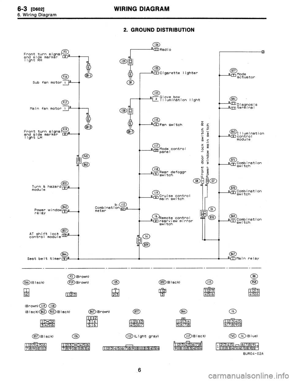
Page 176 of 2890

6-3
[0602
WIRING
DIAGRAM
6
.
Wiring
Diagram
2
.
GROUND
DISTRIBUTION
i26
RedioFront
turn
signal
F3
end
side
marker
rm
light
RH
i
i29
i25
~~--
--
a
--~~
Cigarette
lighter
sB77
Mode
F16
~-~
E
I
actuator
Subfan
motor
i
O
Main
fan
motor
Front
turn
signs
Dend
side
marker
123-1
light
LH
832
Turn
&hazardmodule
Power
wi
relay
AT
shift
lock
857
control
module
(28
:
E
GB-2
FGS
B62
b
:
ill
Combination
meter
(4
m
839
Seat
belt
t
i
mer
C',"-i
F3
(BrowN
O66
(B
I
BC
k)
F19
(Brown)
123
(Brown)
fig
118
(B
I
ac
k)
B43
R15
(B
I
ec
k)
1
2
1
3
1
4
151
6
i
25
1
23
i23
rGlove
box
L~
Illum(nation
light
Fan
switch
L
!-
+'
3
N
NC
i
l7'Z
00
Mode
control
o
panel
0o
~c
'0o
3
il8
4-
L
3
Rear
defoggr
~
o3
switch
O
~m~
07
m
119
Cruise
control
mainswitch
G)§emote
ontro
I
c
LM
rearv
i
e
irror
switch
(g)
(B
I
ec
k)
CD
1
23
4
M
S6
(g)(Brown)
(~D
1
23
[96
R4
;6R7
(~D(BISCK)
(~D
ff~
1516-111
12131><14151
111213
171a191101111121
1718191101111121131141
CD
(L
(ght
gray)
4
'
:F
151617
P911011111~~
D
I
agnos
1
s
Lrm
term
1
na
I
(E~)l
II
um
I
nat
1
on
LEE
contro
I
modu
I
e
(ED
LM
Combination
switch
870
sl=
Combination
switch
B69
Combination
switch
867
-IM
Main
relay
141516
(E)
(a)
1
234
S6JR8
161
r
1
E319
1101
(aD
(B
I
ac
K)
(B
I
u
e)
p
r-1
n
~1
1
F2-1[3
1
f41516
1
7a
0
1
2-
F
-
1q,
[3
46
112-2TI-3114115116117118119120
I'F
BUR04-02A
6
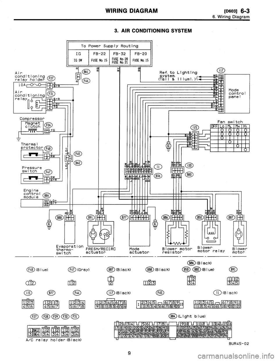
Page 179 of 2890

WIRING
DIAGRAM
[113so31
6-3
6
.
Wiring
Diagram
3
.
AIR
CONDITIONING
SYSTEM
Air
conditioningrelay
holder
F27
Compressor
Magnet
F24
clutch
Thermal
protector
F48
Pressure
switch
Q47
Engine
control
module
l
a
p
To
Power
Supply
Routing
IG
FB-22
FB-32
FB-20
IG
SW
FUSE
Na
15
FUSE
Na20FUSENa
21
FUSE
Na
15
M
11
Evaporation
thermo-
FRESH/RECIRC
switch
actuator
F48
(B
I
ue)
(j~)
(Gr
ay)
(M
FIT2-1
123
45
6
C1-
F2~
n
R3
[4151617
1
234
(~D(~D(~D
(~~D
(E)
j
F1W2-1
1
2
1
2
1
2
1
2-
-
-
MMMM
F3T
i
0
9
4
1
3
4
34
34
34
A/Crelay
holder(Black)
Mode
actuator
Ref
.
to
Lighting
Blower
motor
Blower
resistor
motor
relay
O
(B
I
ac
k)
Blower
motor
B87
(B
I
ac
k)
O
(B
I
ac
k)
B50880
(B
I
ue)
B91
1
12
1
2
123
34
345
i
ll
(B
I
ac
k)F45
1
l
(B
I
ac
k)
1
234S
I
6
1
7
1
12345
b789
125
6789(0
34
I1121314t516171819202122
1
9
1
10
1
11
1
12
1
13
1
14
1
15
1
t6
111121314t51617t81920~~
BB4
(L
t
ght
b
I
ue)
12U34
U
56
U
78
U
U
9l0
U
Ilt2
U
1314LJ1516
17
1
18
1
19
1
20
1
21
1
22
1
23
1
24
1
25
1
26
1
27
1
28
1
29
1
30
1
31323
3
34
35
3637
38
39
40
4142
43
44454647
1
48
1
49
~
0
1
51
1
52
1
53
1
54
~
5
1
56
1
57
1
M59
1
60
1
61
~
2
1
63
1
64
1
65
1
66
1
67
1
66
1
69
1
7'
7172
73
74
75
76777B7980
81
1
89
1
83
1
84
8
86878889
90
9192
93
94
996
BUR45-02
9
Page 182 of 2890
6-3
[Dso131
WIRING
DIAGRAM
6
.
Wiring
Diagram
Combination
meter
Tachometer
i10
:a
-
110
OD
:
b
Malfunction
i14
I:
c
indicator
~}g
lamp
Speedometer
circuit
ill
Main
relay
o
B47
Twisted
wire
0
B46
E
Fuel
pump
relay
13
.
ENGINE
ELECTRICAL
SYSTEM
To
Power
Supply
Routing
FB-20
~
MB-3
~
FB-4
~
ST
FB-22
Check
FUSENa
15
SBF-2
FUSE
Na
l6IGSW
FUSE
W
15
connector
a
v
B79
,~l,,I
F45
u
B62(2
837
i3
B3B
S
.
M
.
J
.
[Referto
foldout
page
.]
R58R57Rt5
Fuel
M
Y
pump
E
Inhibitor
switch
Bl2
B97817
RI
Vehicle
speed
sensor
2
B17
(B
I
ac
k)
i
tl
B46
(Green)
R15
(B
I
ac
k)
R58
12
1
2
123
12
12334
3456
456
(
2D
(Light
gray)
110
i
l2
(L
I
ght
gray)
1
1
1
2
1
3
1
4
1
5
1
6
M78
9
1
10
1
11
1
12
1
D
1
1234567891011113141516
rnrnmvo~
v
.»ov
.0m
.OMPPmM
.Oh
l~
Enginecontro
I
B84
module
B47
(Brown)
(g
)(Gray)
1
2
1
23
4
31
45
67
85
1
69
1
16N1
1
12
1
-
(
ED
B79
(Gray)
1
23
4567
89
1
10
1112
1314
t2(3
(B
rown)
234789
12345
678910
l
'
1
11
1
1
2l3l4151617181920~~
lll2(31415t6L71819202122
BUR10-02A
12
Page 186 of 2890
6-3
[oso2s]
WIRING
DIAGRAM
6
.
Wiring
Diagram
23
.
RADIATOR
FAN
SYSTEM
Diode
(A/C)
Main
fan
motor
oi3~
Subfen
motor
C
~
Flb
(B
leCk)
F43
(Orange)
Fl7
(B
I
ec
K)
(~D(~~(~D
QD
1
2
1
2
[3ql2
4
34
P34
34
A/C
relay
holder(Black)
F44
1234
5678
Engine
control
module
al
I
Air
conditioning
relay
holder
10A
F27
Main
fan
relay-1
F28
Ma
i
nfan
F30
Mr
relay-2
Sub
fan
F29
o
D
relay-2
F45
234
6789
1
1112131415161718192010
884
(L
1
ght
b
I
ue)
12
345678
9l0
lit213141516
17181920212
3242526
78
930
313233343
363738394
4142434445464748
1
49
~
1]
1
51
~
2
15
3
1
54
~
5
56
7
58
59
0
6l
62
63
4
65
66
67
68
9
70
7172
7374
7
76
77
78
79
8
8182
83
84
8
96
87
9
9
192
9394
9
96
BUR14-02
16
Page 190 of 2890

r
Connecting
to
)r
Area
No
.
Name
C-4
D1
Front
doorcord
RH
ow
C-4
ABi
SRS
(Airbag)
harness
;k
C-4
Turn
&
hazard
module
.k
C-3
i1
C-3
i2
instrument
panel
wiring
un
C-3
i3
harness
e
C-3
i4
y
C-3
OBD-IIservice
connector
C-3
Power
window
circuit
breaker
C-3
Power
window
relay
;k
C-3
Illuminationcontrol
module
C-3
Seat
belt
timer
;n
B-4
Fuel
pump
relay
vn
B-4
Main
relay
;k
B-4
Horn
relay
B-4
Blower
relay
y
C-4
FIB
y
C-4
B-3
Shield
joint
connector
(AT)
.k
B-3
:k
B-3
Transmission
control
module
.k
B-3
:k
B-3
Shift-lock
control
module
B-4F44
i
h
B-4F45
Front
w
ring
arness
.k
B-3
Stop
light
switch
,k
B-3
Stop
8
brake
switch
(Withcruise
control)
:k
8-3
Cruise
control
sub
switch
Connector
Connecting
to
No
.
Pole
Color
Area
No
.
Name
869
11
Black
C-3
B70
9
C-3
Combination
switch
B71
8
8-3
B72
6
Black
C-3
Ignition
switch
B73
2
Black
B-3
Key
lock
solenoid
B74
2
Black
B-3
Key
warning
switch
B75
2
Green
B-2
876
T
d
B76
2
Green
8-2
875
e
connector
est
mo
877
7
B-2
Mode
actuator
B78
9
Yellow
B-2
Data
link
connector
B79
14
Gray
C-2
Check
connector
BBO
4
Blue
B-2
i20
Instrument
panel
wiring
harness
B81
1
x
2
B-2
Diagnosis
terminal
(Ground)
B82
6
Black
B-2
Diagnosisconnector
BB3
4
C-1
Shield
joint
connector
(EIG)
BBQ
96Lightblue
C-2
Engine
control
module
B85
4
Brown
B-3
Diode
(Lighting)
B86
4
Black
B-1
Blower
motor
resistor
887
2
Black
B-1
Blower
motor
888
3
Black
B-1
Evaporatorthermoswitch
B90
2
Green
B-4
R50
Room
light
cord
B91
5
B-1
FRESHIRECIRC
actuator
B92
8
B-1
Door
lock
timer
894
20
Black
B-1
Cruise
control
module
B97
56
B-4
R1
Rear
wiring
harness
(S.M
.J
.)
B101
24
B-1
D11
Front
door
cord
LH
8111
3
Gray
C-4FIB
`
:
Non-colored
4
.
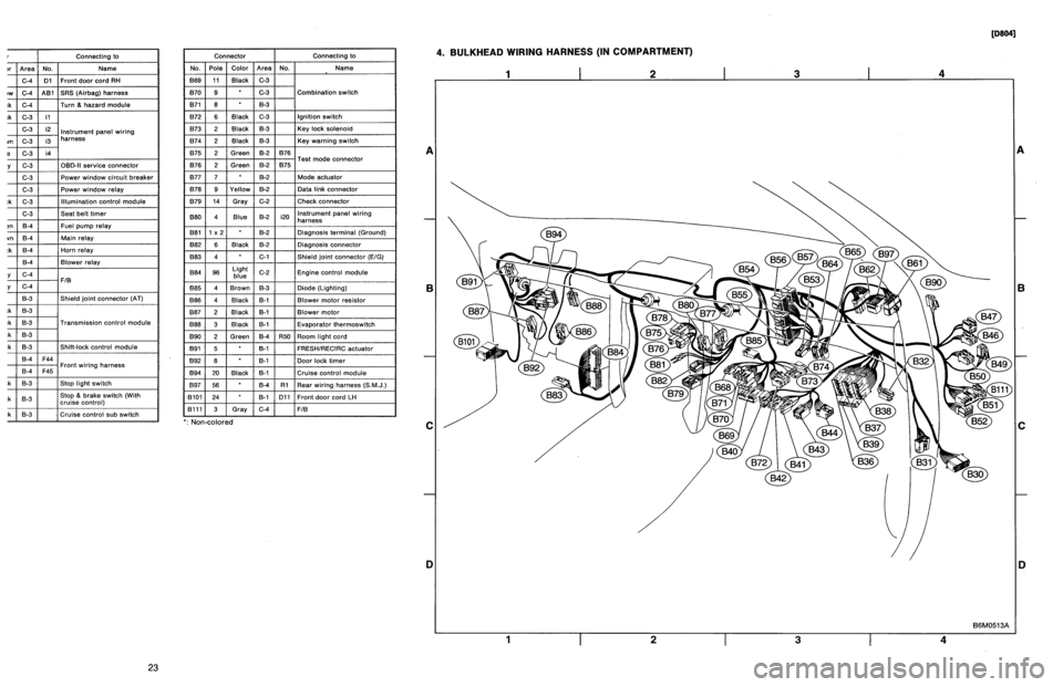
BULKHEAD
WIRING
HARNESS
(IN
COMPARTMENT)
1
I
2
I
3
I
4
A
B
C
D
1
I
2
I
3
I
4
[oeo41
B6M0513A
A
B
C
iJ
23
Page 191 of 2890

Connector
Connecting
to
No
.
Pole
Color
Area
No
.
Name
830
24
C-4
D1
Front
door
cord
RH
831
7
Yellow
C-4
A81
SRS
(Airbag)
harness
B32
3
Black
C-4
Turn
&
hazard
module
B36
22
Black
C-3
i1
B37
22
C-3
i2
Instrument
panel
wiring
B38
22
Brown
C-3
i3
harness
B39
20Blue
C-3
i4
B40
16
Gray
C-3
OBD-II
service
connector
B41
2
C-3
Power
window
circuit
breaker
842
4
C-3
Power
window
relay
B43
6
Black
C-3
Illumination
control
module
B44
8
C-3
Seat
belt
timer
B46
4
Green
B-4
Fuel
pump
relay
B47
6
Brown
B-4
Main
relay
B49
3
Black
B-4
Horn
relay
850
4
B-4
Blower
relay
851
11
Gray
C-4
FIB
B52
12
Gray
C-4
853
4
B-3
Shield
joint
connector
(AT)
B54
12
Black
B-3
B55
16
Black
B-3
Transmission
control
module
B56
20
Black
B-3
B57
12
Black
B-3
Shift-lock
control
module
861
B
B-4
F44
B62
20
B-4
F45
Front
wiring
harness
B64
2
Black
B-3
Stop
light
switch
B65
4
Black
B-3
Stop
&
brake
switch(Withcruise
control)
B68
5
i
Black
i
B-3
Cruise
control
sub
switch
Connector
Connecting
to
No
.
Pole
Color
Area
No
.
Name
B69
11
Black
C-3
B70
9
C-3
Combination
switch
B71
8
8-3
B72
6
Black
C-3
Ignition
switch
B73
2
Black
B-3
Key
lock
solenoid
B74
2
Black
B-3
Key
warning
switch
B75
2
Green
B-2
B76
B76
2
Green
&2
B75
Test
mode
connector
B77
7
B-2
Made
actuator
B78
9
Yellow
B-2
Data
link
connector
B79
14
Gray
C-2
Check
connector
B80
4
Blue
B-2
i20
Instrumentpanel
wiring
harness
B81
1
x
2
B-2
Diagnosis
terminal
(Ground)
B82
6
Black
B-2
Diagnosis
connector
B83
4
C-1
Shield
joint
connector
(E!G)
884
96
Light
blue
C-2
Engine
control
module
885
4
Brown
B-3
Diode
(Lighting)
B86
4
Black
B-1
Blower
motor
resistor
887
2
Black
B-1
Blower
motor
B88
3
Black
8-t
Evaporator
thermoswitch
890
2
Green
B-4
R50
Room
light
cord
B91
5B-1
FRESHIRECIRC
actuator
892
8
B-1
Door
lock
timer
B94
20
Black
B-1
Cruise
control
module
B97
56
B-4
R1Rear
wiring
harness
(S
.M
.J
.)
B101
24
B-1
D11
Front
doorcord
LH
13111
3
Gray
C-4
FIB
`
:
Non-colored
4
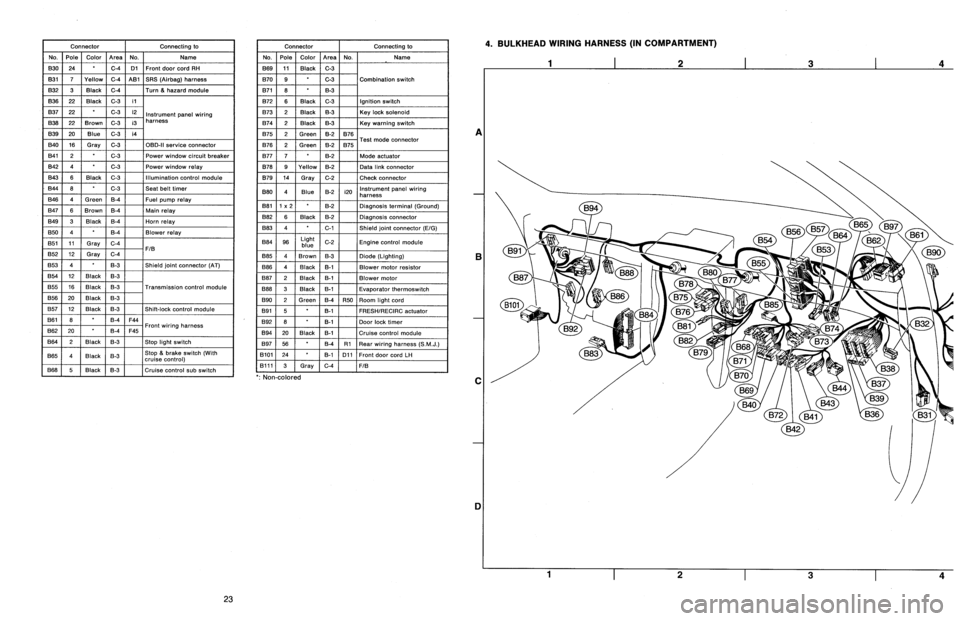
.
BULKHEAD
WIRING
HARNESS
(IN
COMPARTMENT)
A
B
C
1]
4
23
Page 215 of 2890
2-7
[reioi
ON-BOARD
DIAGNOSTICS
II
SYSTEM
8
.
Diagnostics
for
Engine
Starting
Failure
8
.
Diagnostics
for
Engine
Starting
Failure
I:
FUEL
PUMP
CIRCUIT
(2200
cc
AWD
EXCEPT
TAIWANMODEL)
811
Check
operating
sound
offuel
pump
.
812
Checkground
circuit
offuel
pump
.
I
__
813
Check
power
supply
to
fuel
pump
.
1
814
Check
harness
between
fuel
pump
and
fuel
pump
relay
connector
.
815
[
Check
fuel
pump
relay
.
816
Check
harness
between
ECM
and
fuel
pump
relay
connector
.
CAUTION
:
After
repair
or
replacement
of
faulty
parts,
conduct
CLEAR
MEMORY
and
INSPECTION
MODES
.
Ref
.
to
2-7
[T3D0]
and
[T3E0]
.*2
and
*4
>
4