Page 216 of 2890
![SUBARU LEGACY 1996 Service Repair Manual
ON-BOARD
DIAGNOSTICS
II
SYSTEM
[rsi2]
2-7
8
.
Diagnostics
for
Engine
Starting
Failure
WIRING
DIAGRAM
:
Fuel
pump
M
R58
S
.M
.J
.
R67R46
R1
897
E
B84
ECM
Fuel
pump
relay
0
846
SBF-2
No
.1 SUBARU LEGACY 1996 Service Repair Manual
ON-BOARD
DIAGNOSTICS
II
SYSTEM
[rsi2]
2-7
8
.
Diagnostics
for
Engine
Starting
Failure
WIRING
DIAGRAM
:
Fuel
pump
M
R58
S
.M
.J
.
R67R46
R1
897
E
B84
ECM
Fuel
pump
relay
0
846
SBF-2
No
.1](/manual-img/17/57433/w960_57433-215.png)
ON-BOARD
DIAGNOSTICS
II
SYSTEM
[rsi2]
2-7
8
.
Diagnostics
for
Engine
Starting
Failure
WIRING
DIAGRAM
:
Fuel
pump
M
R58
S
.M
.J
.
R67R46
R1
897
E
B84
ECM
Fuel
pump
relay
0
846
SBF-2
No
.16
~b---
862F45
884
9
10
1112
13141516
R58
R61B46
3132
333435363738
39
40
4142
43
44585960
6162
6364
6566
6768
6910
1
2
3
~1
]
M34
1
84
1
8
51
86
1
871
88
1
89
1
90
1
91
1
92
1
93
1
94
1
95
1
96
1
4
56~J
82M
1014
PUMpK
OPERATING
SOUND
OFFUEL
811
CHEC
R58
OBD0132A
Make
sure
that
fuel
pump
isin
operation
for
two
seconds
when
turning
ignition
switch
to
ON
.
CHECK
:
Does
fuel
pump
produce
operating
sound?
NOTE
:
Fuel
pump
operation
check
can
also
beexecuted
using
Subaru
Select
Monitor
(Function
mode
:
FD01)
.
For
the
procedure,
referto
"COMPULSORY
VALVE
OPER-
ATION
CHECK
MODE"
2-7
[T3F0]*4
.
,res
:
Check
fuel
injector
circuit
.
<
Ref
.
to
2-7
[T10Q0].*2
>
No
:
Go
to
step
812
.
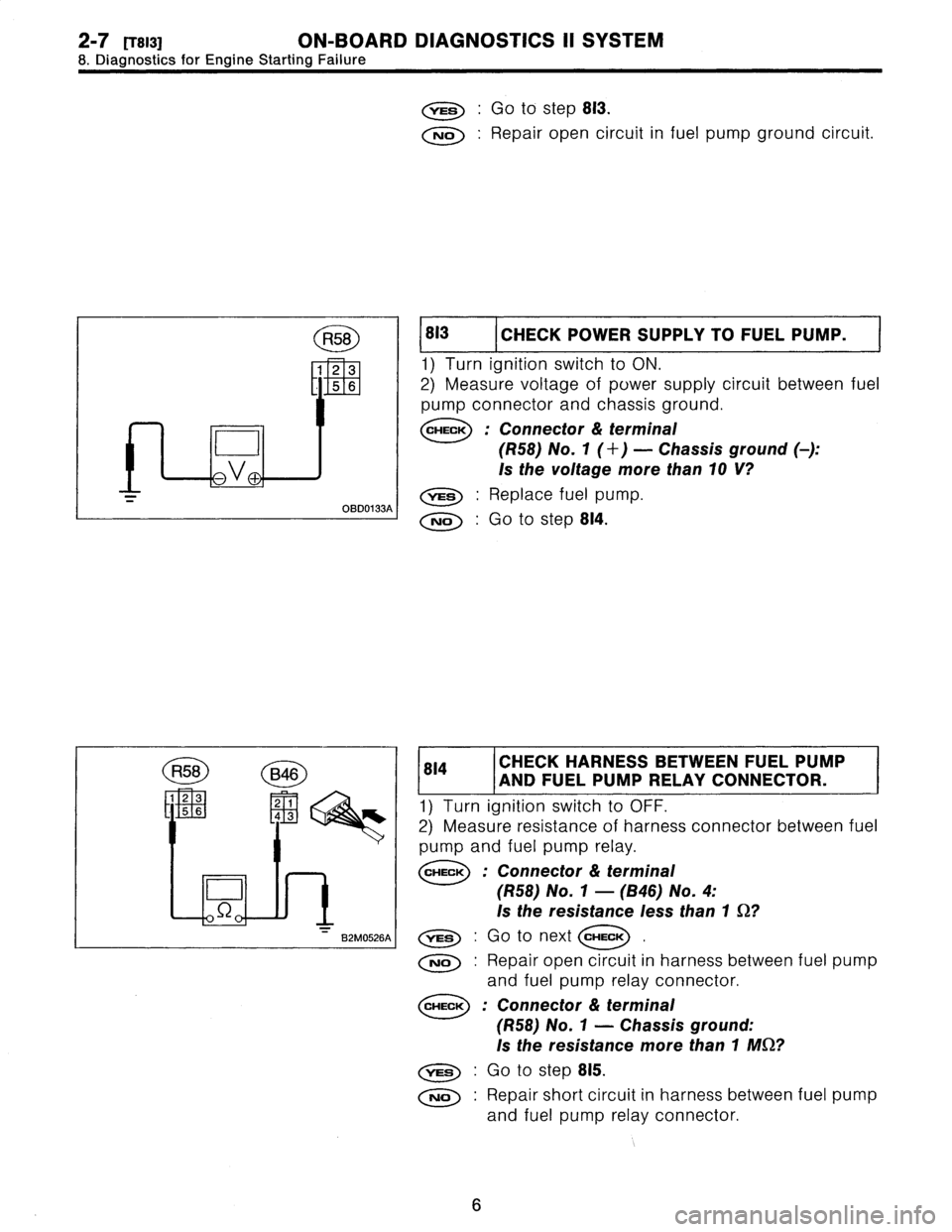
1
812
CHECK
GROUND
CIRCUIT
OF
FUEL
PUMP
.
1)
Turn
ignition
switch
to
OFF
.
2)
Disconnect
connector
from
fuel
pump
.
3)
Measure
resistance
of
harness
connector
between
fuel
pump
and
chassis
ground
.
CHECK
:
Connector
&
terminal
(R58)
No
.
4
-
Chassis
ground
:
Is
the
resistance
less
than
5
S2?
5
Page 217 of 2890

2-7
trsi31
ON-BOARD
DIAGNOSTICS
II
SYSTEM
8
.
Diagnostics
for
Engine
Starting
Failure
R58
Bog
1
23
2
1
L
11
5
643
D
S2
B2M0526A
,rES
:
Go
to
step
813
.
No
:
Repair
open
circuit
in
fuel
pump
ground
circuit
.
813
I
CHECK
POWER
SUPPLY
TOFUEL
PUMP
.
1)
Turn
ignition
switch
to
ON
.
2)
Measure
voltage
of
power
supply
circuit
between
fuel
pump
connector
and
chassis
ground
.
CHECK
:
Connector
&
terminal
(R58)
No
.
1
(+)
-
Chassis
ground
(
)
:
Is
the
voltage
more
than10
V?
,rES
:
Replace
fuel
pump
.
No
:
Go
to
step
814
.
814
CHECK
HARNESS
BETWEEN
FUEL
PUMP
AND
FUEL
PUMP
RELAY
CONNECTOR
.
1)
Turn
ignition
switch
to
OFF
.
2)
Measure
resistance
of
harness
connector
between
fuel
pump
and
fuel
pump
relay
.
CHECK
:
Connector
&
terminal
(R58)
No
.
1
-
(B46)
No
.
4
:
Is
the
resistance
less
than
1
S2?
,rES
:
Go
to
next
CHECK
No
:
Repair
open
circuit
in
harness
between
fuel
pump
and
fuel
pump
relay
connector
.
CHECK
:
Connector
&
terminal
(R58)
No
.
1
-
Chassis
ground
:
Is
the
resistance
more
than
1
MS2?
,res
:
Go
to
step
815
.
No
:
Repair
short
circuit
in
harness
between
fuel
pump
and
fuel
pump
relay
connector
.
6
Page 218 of 2890

ON-BOARD
DIAGNOSTICS
II
SYSTEM
[Tsisl
2-7
8
.
Diagnostics
for
Engine
Starting
Failure
815
1
CHECK
FUEL
PUMP
RELAY
.
1)
Disconnectconnectors
from
fuel
pump
relay
and
main
relay
.
2)
Remove
fuel
pump
relay
and
main
relay
with
bracket
.
3)
Connect
battery
to
fuel
pump
relay
connector
terminals
No
.
1
and
No
.
3
.
4)
Measure
resistance
between
connector
terminals
of
fuel
pump
relay
.
CHECK
;
Terminals
No
.
2
-
No
.
4
:
Is
the
resistance
less
than10
92?
YES
:
Go
tostep
816
.
No
:
Replace
fuel
pump
relay
.
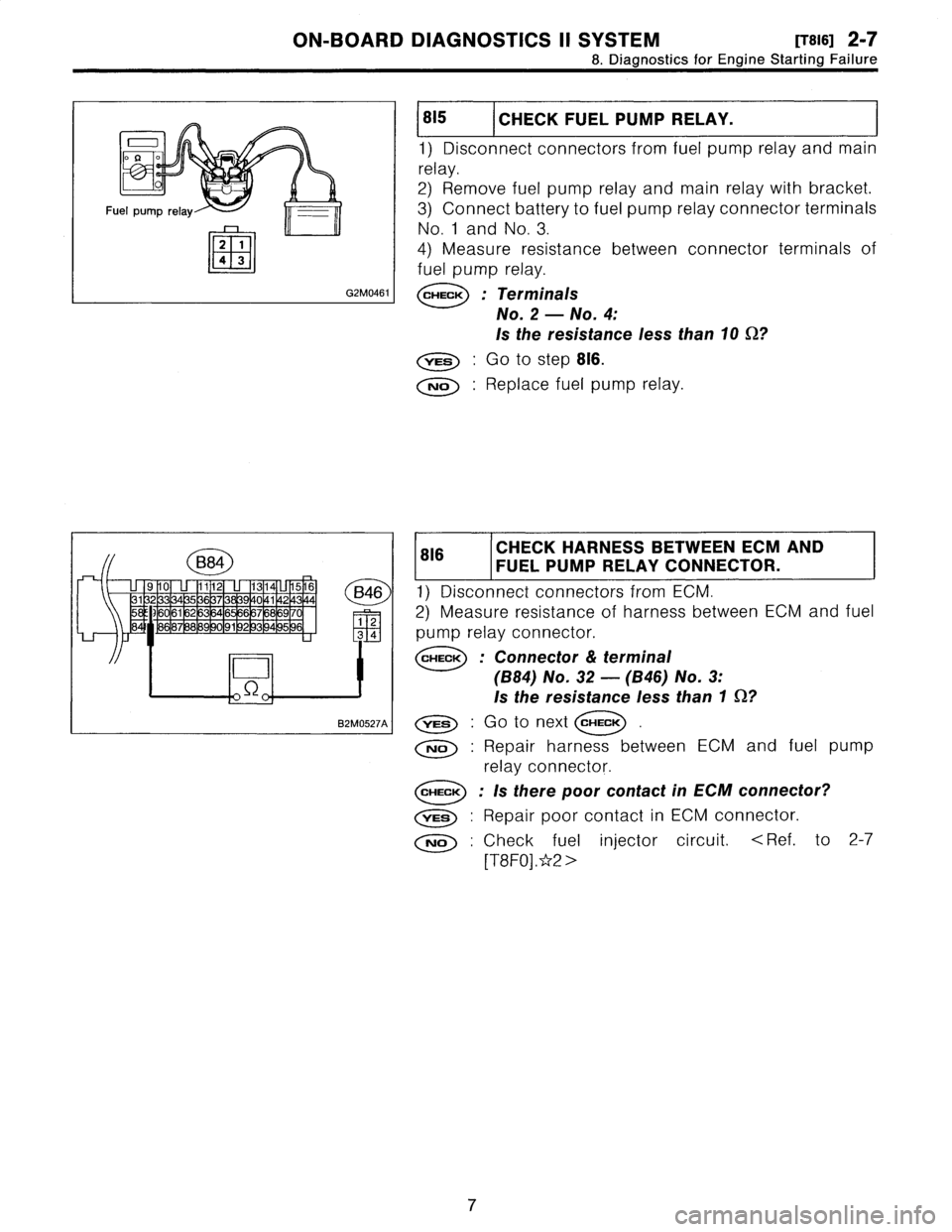
816
CHECK
HARNESS
BETWEEN
ECM
FUEL
PUMP
RELAY
CONNECTOR
.
AND
1)
Disconnectconnectors
from
ECM
.
2)
Measure
resistanceof
harness
between
ECM
and
fuel
pump
relay
connector
.
CHECK
:
Connector
&
terminal
(B84)
No
.
32
-
(B46)
No
.
3
:
Is
the
resistance
less
than
1
0?
YES
.
Go
to
next
CHECK
No
:
Repair
harness
between
ECM
and
fuel
pump
relay
connector
.
CHECK
:
Is
there
poor
contact
in
ECM
connector?
vES
:
Repair
poor
contact
in
ECM
connector
.
No
:
Check
fuel
injector
circuit
.
<
Ref
.
to
2-7
[T8F0]
.*2
>
7
Page 220 of 2890
![SUBARU LEGACY 1996 Service Repair Manual
ON-BOARD
DIAGNOSTICS
11
SYSTEM
[T10A0]
2-7
10
.
Diagnostics
Chart
with
Trouble
Code
DTC
No
.
Abbreviation
(Subaru
select
monitor)Item
Page
P0500
VSP
Vehicle
speed
sensor
malfunction
1
P0505
I SUBARU LEGACY 1996 Service Repair Manual
ON-BOARD
DIAGNOSTICS
11
SYSTEM
[T10A0]
2-7
10
.
Diagnostics
Chart
with
Trouble
Code
DTC
No
.
Abbreviation
(Subaru
select
monitor)Item
Page
P0500
VSP
Vehicle
speed
sensor
malfunction
1
P0505
I](/manual-img/17/57433/w960_57433-219.png)
ON-BOARD
DIAGNOSTICS
11
SYSTEM
[T10A0]
2-7
10
.
Diagnostics
Chart
with
Trouble
Code
DTC
No
.
Abbreviation
(Subaru
select
monitor)Item
Page
P0500
VSP
Vehicle
speed
sensor
malfunction
'1
P0505
ISC
Idle
control
system
malfunction
`1
P0506
ISC
-
L
Idle
control
system
RPM
lower
than
expected
'1
P0507
ISC
-
H
Idle
control
system
RPM
higher
than
expected
'1
P0600
-
Serial
communication
link
malfunction
`1
P0601
RAM
Internal
control
module
memory
check
sum
error
'1
P0703
ATBRK
Brake
switch
input
malfunction
'1
P0705
ATRNG
Transmissionrange
sensor
circuit
malfunction
`1
P0710
ATF
Transmission
fluid
temperature
sensor
circuit
malfunction
'1
P0720
ATVSP
Output
speed
sensor
(vehicle
speed
sensor
1)
circuit
malfunction
'1
P0725
ATNE
Engine
speed
input
circuit
malfunction
'1
P0731
ATGR1
Gear
1
incorrect
ratio
P0732
ATGR2
Gear
2
incorrect
ratio
"
1
P0733
ATGR3
Gear
3
incorrect
ratio
P0734
ATGR4
Gear
4
incorrect
ratio
P0740
ATLU
-
F
Torque
converter
clutch
system
malfunction
1
P0743
ATLU
Torque
converter
clutch
system
electrical
*1
P0748
ATPL
Pressure
control
solenoid
electrical
'1
P0753
ATSFTi
Shift
solenoid
A
electrical
`1
P0758
ATSFT2
Shift
solenoid
B
electrical
'1
P0760
ATOVR
-
F
Shift
solenoid
C
malfunction
'1
P0763
ATOVR
Shift
solenoid
C
electrical
'1
P1100
ST-SW
Starter
switch
circuit
malfunction
'1
P1101
N/P
-
SW
Neutral
position
switch
circuit
malfunction
[MT
vehicles]
'1
P1101
N/P
-
SW
Neutral
position
switch
circuit
malfunction
[AT
vehicles]
1
P1102
BR
Pressure
sources
switching
solenoid
valve
circuit
malfunction
'1
P1103
TRQ
Engine
torque
control
signal
circuit
malfunction
`1
P1400
PCVSOL
Fueltank
pressure
control
solenoid
valve
circuit
malfunction
38
P1401
PCV
-
FFueltank
pressure
control
system
function
problem
44
P1402
FIVL
Fuel
level
sensor
circuit
malfunction
46
P1500
FAN
-
1
Radiator
fan
relay
1
circuit
malfunction
'1
P1502
FAN
-
F
Radiator
fan
function
problem
'1
P1700
ATTH
Throttle
position
sensor
circuit
malfunction
for
automatic
transmission
'1
P1701
ATCRS
Cruise
control
set
signal
circuit
malfunction
for
automatic
transmission
'1
P1702
ATDIAG
Automatic
transmission
diagnosis
inputsignal
circuit
malfunction
'1
P0461'2
EXERR22
Fuel
level
sensor
circuit
range/performance
problem
56
"1
:
<
Ref
.
to
2-7
[T11A0]
.*4
>
'2
:
Only
OBD-II
general
scan
tool
displays
DTC
.
Page 230 of 2890
ON-BOARD
DIAGNOSTICS
II
SYSTEM
ITyoso2i
2-7
10
.
DiagnosticsChart
with
Trouble
Code
WIRING
DIAGRAM
:
Main
relay
0
0
847
884
77
ECM
V
897
R69
S
.M
.J
.
~°c~
Vent
control
solenoid
valve
R68
R57R15
Pressure
control
862F45
SBF-2
O~C)-
B
~E
822
O
E4
Purge
control
solenoid
valve
--{~J
solenoid
valve
B84R68
R69
R57847
822
E4
1
U
49
10
11
1
1314
1
16
1
234
171
1
811
9
12012112212
1113
63
1
36
44
444
M56
5678
49
1
63
55116
68
/Ul
1
3
9101112
9
19
~Lltu
~
4L_L51bIJ~l
13141516
B2M1017
10BQ1
I
CHECK
ANY
OTHER
DTC
(BESIDES
DTC
P0440)
ON
DISPLAY
.
Is
there
any
other
DTC
on
display?
Inspect
the
relevant
DTC
using
"10
.
Diagnostics
Chart
with
Trouble
Code,
2-7
[T10A0]"*7
.
No
:
Go
to
step
101302
.
FILLER
PIPE
.
FILLER
CAPAND
FUEL
1)
Turn
ignition
switch
to
OFF
.
2)
Open
the
fuelflap
.
CHECK
:
Is
the
fuel
filler
cap
tightened
securely?
Tighten
fuel
filler
cap
securely
.
o
:
Go
to
next
CHECK
.
19
Page 234 of 2890
ON-BOARD
DIAGNOSTICS
11
SYSTEM
[rIoBROi
2-7
10
.
Diagnostics
Chart
with
Trouble
Code
WIRING
DIAGRAM
:
Main
relay
0
0
B41
B61F45
SBF-2
B84
~
ECM
S
.M
.J
Vent
control
.
solenoid
897
Rt
R15
R57
R69
valve
Canister
O
B47R57
R69
U
910
U
1112
U
1314L11516
3132
3334353637383940
4142
4344
1
2
6162
63
64656667
68
6970
34
1
lu
//j848586
8788
8990
9192
93
949596
56
B2M1018
23
Page 237 of 2890
2-7
['r10BR5]
ON-BOARD
DIAGNOSTICS
II
SYSTEM
10
.
Diagnostics
Chart
with
Trouble
Code
R69
E
11U2
D
H2M1241C
I
10BR5
CHECK
I
TROL
SOL
NOID
SUPPLY
VALVE,TO
VENT
CON-
1)
Turn
ignition
switch
to
ON
.
2)
Measure
voltage
between
vent
control
solenoid
valve
and
chassis
ground
.
CHECK
:
Connector
&
terminal
(R69)
No
.
1
(+)
-
Chassis
ground
(
)
:
Is
the
voltage
more
than10
V?
Go
to
next
CHECK
No
:
Repair
harness
and
connector
.
NOTE
:
In
this
case,
repair
the
following
:
e
Open
circuit
in
harness
between
main
relay
and
vent
control
solenoid
valve
"
Poor
contact
in
coupling
connectors
(B97
and
R57)
"
Poor
contact
in
main
relay
connector
CHECK
:
Is
there
poor
contact
in
vent
control
solenoid
valve
connector?
vss
:
Repair
poor
contact
in
vent
control
solenoid
valve
connector
.
No
:
Contact
with
SOA
service
.
NOTE
:
Inspection
by
DTM
is
required,
because
probable
cause
is
deteriorationof
multiple
parts
.
26
Page 250 of 2890
ON-BOARD
DIAGNOSTICS
II
SYSTEM
[T10BU0]
2_7
10
.
DiagnosticsChart
with
Trouble
Code
WIRING
DIAGRAM
:
Main
relay
0
0
~
frF
847
ECM
TIT
-
862F45
SBF-2
r=
--
S
.M
.J
.
897
R1
R15
R57
R68
Fuel
tankpressure
control
solenoid
va
ve
91
0
1
31132133134135
581591~601r6l!62
r-
-
~
483
6
7
U8
.
P516
-Ll
//j
U
1321V11020
39