Page 1638 of 2543

ON±VEHICLE INSPECTION
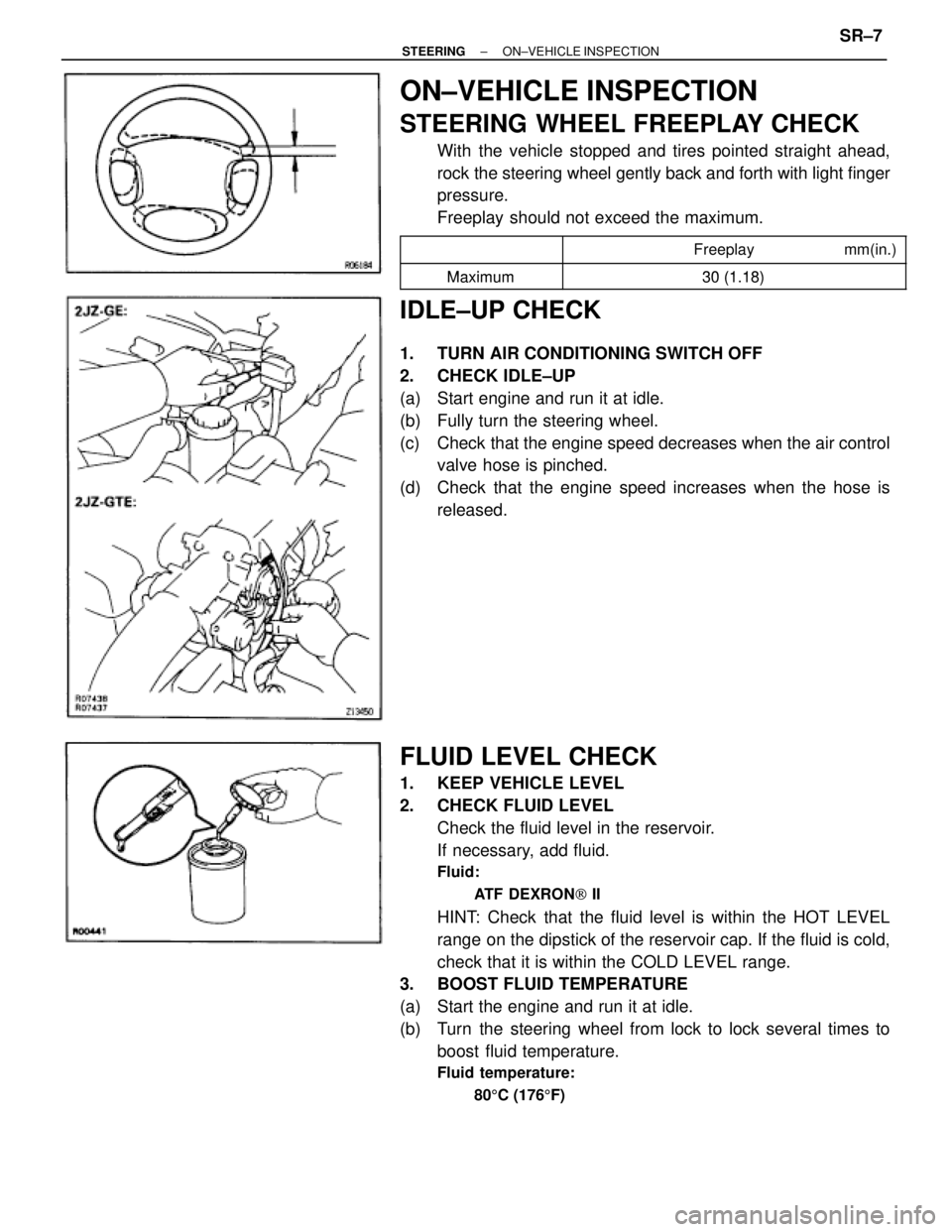
STEERING WHEEL FREEPLAY CHECK
With the vehicle stopped and tires pointed straight ahead,
rock the steering wheel gently back and forth with light finger
pressure.
Freeplay should not exceed the maximum.
�������� �
�������
��������������� �
�������������� Freeplay mm(in.)�������� ��������
Maximum30 (1 18)�������� ��������Maximum30 (1.18)
IDLE±UP CHECK
1. TURN AIR CONDITIONING SWITCH OFF
2. CHECK IDLE±UP
(a) Start engine and run it at idle.
(b) Fully turn the steering wheel.
(c) Check that the engine speed decreases when the air control
valve hose is pinched.
(d) Check that the engine speed increases when the hose is
released.
FLUID LEVEL CHECK
1. KEEP VEHICLE LEVEL
2. CHECK FLUID LEVEL
Check the fluid level in the reservoir.
If necessary, add fluid.
Fluid:
ATF DEXRON[ II
HINT: Check that the fluid level is within the HOT LEVEL
range on the dipstick of the reservoir cap. If the fluid is cold,
check that it is within the COLD LEVEL range.
3. BOOST FLUID TEMPERATURE
(a) Start the engine and run it at idle.
(b) Turn the steering wheel from lock to lock several times to
boost fluid temperature.
Fluid temperature:
805C (1765F)
± STEERINGON±VEHICLE INSPECTIONSR±7
Page 1639 of 2543

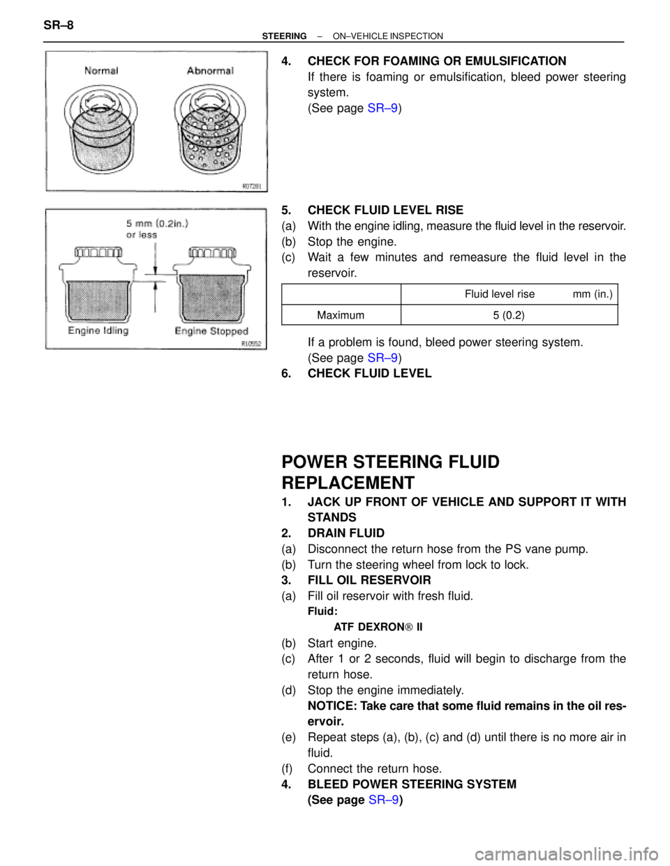
4. CHECK FOR FOAMING OR EMULSIFICATION
If there is foaming or emulsification, bleed power steering
system.
(See page SR±9)
5. CHECK FLUID LEVEL RISE
(a) With the engine idling, measure the fluid level in the reservoir.
(b) Stop the engine.
(c) Wait a few minutes and remeasure the fluid level in the
reservoir.
�������� �
������� ��������
�������������� �
������������� �������������� Fluid level rise mm (in.)
��������Maximum5(02)�������� ��������Maximum5 (0.2)
If a problem is found, bleed power steering system.
(See page SR±9)
6. CHECK FLUID LEVEL
POWER STEERING FLUID
REPLACEMENT
1. JACK UP FRONT OF VEHICLE AND SUPPORT IT WITH
STANDS
2. DRAIN FLUID
(a) Disconnect the return hose from the PS vane pump.
(b) Turn the steering wheel from lock to lock.
3. FILL OIL RESERVOIR
(a) Fill oil reservoir with fresh fluid.
Fluid:
ATF DEXRON[ II
(b) Start engine.
(c) After 1 or 2 seconds, fluid will begin to discharge from the
return hose.
(d) Stop the engine immediately.
NOTICE: Take care that some fluid remains in the oil res-
ervoir.
(e) Repeat steps (a), (b), (c) and (d) until there is no more air in
fluid.
(f) Connect the return hose.
4. BLEED POWER STEERING SYSTEM
(See page SR±9) SR±8
± STEERINGON±VEHICLE INSPECTION
Page 1640 of 2543
POWER STEERING SYSTEM BLEEDING
1. JACK UP FRONT OF VEHICLE AND SUPPORT IT WITH
STANDS
2. TURN STEERING WHEEL
With the engine stopped, turn the steering slowly from lock
to lock several times.
NOTICE: Take care that some fluid remains in the oil res-
ervoir.
3. LOWER VEHICLE
4. START ENGINE
Run the engine at idle for a few minutes.
5. TURN STEERING WHEEL
(a) With the engine at idling, turn the wheel to left or right full lock
and keep it there for 2±3 seconds, then turn the wheel to the
opposite full lock and keep it there for 2±3 seconds.
(b) Repeat (a) several times.
6. STOP ENGINE
7. CHECK FOR FOAMING OR EMULSIFICATION
If the system has to be bled twice specifically because of
foaming or emulsification, check for fluid leaks in the system.
8. CHECK FLUID LEVEL
(See page SR±7)
± STEERINGON±VEHICLE INSPECTIONSR±9
Page 1641 of 2543
FLUID PRESSURE CHECK
1. CONNECT OIL PRESSURE GAUGE
(a) Disconnect the pressure feed tube from the PS vane pump.
(See page SR±26)
(b) Connect the gauge over a new gasket, as shown below.
NOTICE: Check that the valve of the gauge is in the open
position.
2. BLEED POWER STEERING SYSTEM
(See page SR±9)
3. BOOST FLUID TEMPERATURE
(a) Start the engine and run it at idle.
(b) Turn the steering wheel from lock to lock several times to
boost fluid temperature.
Fluid temperature:
805C (1765F)
4. CHECK FLUID PRESSURE READING WITH VALVE
CLOSED
With the engine idling, close the oil pressure gauge valve and
observe the reading on the gauge.
������� ���������������������� ��������������� Fluid pressure kPa (kgf/cm2, psi)
������� �������Minimum7 355 (75 1 067)
�������
Minimum7,355 (75, 1,067)
NOTICE:
wDo not keep the valve closed for more than 10
seconds.
wDo not let the fluid temperature become too high. SR±10
± STEERINGON±VEHICLE INSPECTION
Page 1642 of 2543

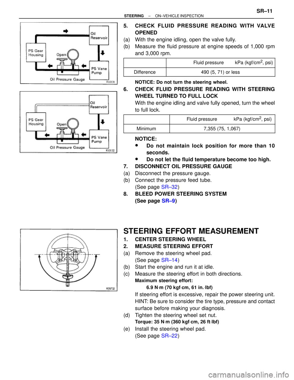
5. CHECK FLUID PRESSURE READING WITH VALVE
OPENED
(a) With the engine idling, open the valve fully.
(b) Measure the fluid pressure at engine speeds of 1,000 rpm
and 3,000 rpm.
������� �
������ �������
���������������� �
��������������� ����������������Fluid pressure kPa (kgf/cm2, psi)
������� �������Difference���������������� ����������������490 (5, 71) or less
NOTICE: Do not turn the steering wheel.
6. CHECK FLUID PRESSURE READING WITH STEERING
WHEEL TURNED TO FULL LOCK
With the engine idling and valve fully opened, turn the wheel
to full lock.
������� ����������������������� ���������������� Fluid pressure kPa (kgf/cm2, psi)������� �
������ �������Minimum
���������������� �
��������������� ����������������7,355 (75, 1,067)
NOTICE:
wDo not maintain lock position for more than 10
seconds.
wDo not let the fluid temperature become too high.
7. DISCONNECT OIL PRESSURE GAUGE
(a) Disconnect the pressure gauge.
(b) Connect the pressure feed tube.
(See page SR±32)
8. BLEED POWER STEERING SYSTEM
(See page SR±9)
STEERING EFFORT MEASUREMENT
1. CENTER STEERING WHEEL
2. MEASURE STEERING EFFORT
(a) Remove the steering wheel pad.
(See page SR±14)
(b) Start the engine and run it at idle.
(c) Measure the steering effort in both directions.
Maximum steering effort:
6.9 NVm (70 kgfVcm, 61 in.Vlbf)
If steering effort is excessive, repair the power steering unit.
HINT: Be sure to consider the tire type, pressure and contact
surface before making your diagnosis.
(d) Tighten the steering wheel set nut.
Torque: 35 NVm (360 kgfVcm, 26 ftVlbf)
(e) Install the steering wheel pad.
(See page SR±22)
± STEERINGON±VEHICLE INSPECTIONSR±11
Page 1657 of 2543
POWER STEERING VANE PUMP
REMOVAL
1. REMOVE ENGINE UNDER COVER
Remove the 10 screws.
2. REMOVE BATTERY
3. 2JZ±GTE:
REMOVE AIR HOSE NO.5
4. 2JZ±GTE:
DISCONNECT OIL RESERVOIR TO PUMP HOSE
NOTICE: Take care not to spill fluid on the A/C compres-
sor rotor.
5. 2JZ±GE:
DISCONNECT RETURN TUBE
NOTICE: Take care not to spill fluid on the A/C compres-
sor rotor.
6. 2JZ±GTE:
REMOVE VANE PUMP PULLEY
Using SST to stop the pulley rotating, remove the nut.
SST 09960±10010
7. REMOVE PRESSURE FEED TUBE
Using a spanner (24 mm) to hold the pressure port union, re-
move the union bolt and gasket.
8. REMOVE PS VANE PUMP ASSEMBLY
Remove the 2 bolts.
POWER STEERING VANE PUMP
DISASSEMBLY
NOTICE: When using a vise, do not overtighten it.
1. 2JZ±GE:
REMOVE VANE PUMP PULLEY
Using SST to stop the pulley rotating, remove the nut.
SST 09960±10010 SR±26
± STEERINGPOWER STEERING VANE PUMP
Page 1663 of 2543
15. 2JZ±GE:
INSTALL VANE PUMP PULLEY
Using SST to stop the pulley rotating, torque the nut.
SST 09960±10010
Torque: 43 NVm (440 kgfVcm, 32 ftVlbf)
POWER STEERING VANE PUMP
INSTALLATION
1. INSTALL VANE PUMP ASSEMBLY
Torque the 2 bolts.
Torque: 58 NVm (590 kgfVcm, 42 ftVlbf)
2. CONNECT PRESSURE FEED TUBE
Using a spanner (24 mm) to hold the pressure port union,
torque the union bolt with a new gasket.
HINT: Make sure the stopper is touching the pump housing
as shown, then torque the union bolt.
Torque: 49 NVm (500 kgfVcm, 36 ftVlbf)
3. 2JZ±GTE:
INSTALL VANE PUMP PULLEY
Using SST to stop the pulley rotating, torque the nut.
SST 09960±10010
Torque: 43 NVm (440 kgfVcm, 32 ftVlbf)
4. 2JZ±GE:
CONNECT RETURN TUBE
5. 2JZ±GTE:
CONNECT OIL RESERVOIR TO PUMP HOSE
6. 2JZ±GTE:
INSTALL AIR HOSE NO.5
7. INSTALL BATTERY
8. INSTALL ENGINE UNDER COVER
Install the 10 screws. SR±32
± STEERINGPOWER STEERING VANE PUMP
Page 1667 of 2543

POWER STEERING GEAR REMOVAL
1. REMOVE ENGINE UNDER COVER
Remove the 10 screws.
2. REMOVE FR SUSPENSION MEMBER PROTECTOR
Remove the 4 bolts.
3. DISCONNECT INTERMEDIATE SHAFT
(See page SR±15)
4. DISCONNECT RH AND LH TIE ROD ENDS
(See page SA±17)
5. DISCONNECT PRESSURE FEED TUBE
Remove the union bolt and gasket.
6. DISCONNECT RETURN TUBE
Remove the union bolt and 2 gaskets.
7. DISCONNECT PPS SOLENOID CONNECTOR
8. REMOVE RACK HOUSING BRACKET AND GROMMET
Remove the 2 bolts and nuts.
9. REMOVE POWER STEERING GEAR ASSEMBLY
Remove the 2 bolts and nuts.
POWER STEERING GEAR
DISASSEMBLY
NOTICE: When using a vise, do not overtighten it.
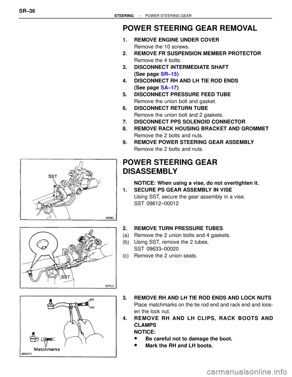
1. SECURE PS GEAR ASSEMBLY IN VISE
Using SST, secure the gear assembly in a vise.
SST 09612±00012
2. REMOVE TURN PRESSURE TUBES
(a) Remove the 2 union bolts and 4 gaskets.
(b) Using SST, remove the 2 tubes.
SST 09633±00020
(c) Remove the 2 union seats.
3. REMOVE RH AND LH TIE ROD ENDS AND LOCK NUTS
Place matchmarks on the tie rod end and rack end and loos-
en the lock nut.
4. REMOVE RH AND LH CLIPS, RACK BOOTS AND
CLAMPS
NOTICE:
wBe careful not to damage the boot.
wMark the RH and LH boots. SR±36
± STEERINGPOWER STEERING GEAR