Page 1588 of 2543
 Install the check valve and seal washer.
NOTICE: Be careful of the check valve and seal washer instal-
lation direction.
(b) Connect these hoses:
wAir")
IAC VALVE INSTALLATION
1. INSTALL IAC VALVE
(a) Install the check valve and seal washer.
NOTICE: Be careful of the check valve and seal washer instal-
lation direction.
(b) Connect these hoses:
wAir hose
wWater bypass hose (from No.2 water bypass pipe)
wWater bypass hose (from No.4 water bypass pipe)
(c) Install a new gasket and the IAC valve with the 2 bolts.
Torque: 21 NVm (210 kgfVcm, 15 ftVlbf)
2. CONNECT IAC VALVE CONNECTOR
3. FILL WITH ENGINE COOLANT
EFI MAIN RELAY
EFI MAIN RELAY INSPECTION
1. REMOVE EFI MAIN RELAY
LOCATION: In the engine compartment relay box.
2. INSPECT EFI MAIN RELAY
A. Inspect relay continuity
(a) Using an ohmmeter, check that there is continuity between
terminals 1 and 2.
(b) Check that there is no continuity between terminals 3 and 5.
If continuity is not as specified, replace the relay.
B. Inspect relay operation
(a) Apply battery voltage across terminals 1 and 2.
(b) Using an ohmmeter, check that there is continuity between
terminals 3 and 5.
If operation is not as specified, replace the relay.
3. REINSTALL EFI MAIN RELAY EG±298
± ENGINESFI SYSTEM (2JZ±GTE)
Page 1589 of 2543
EFI NO.2 RELAY
EFI NO.2 RELAY INSPECTION
1. REMOVE EFI NO.2 RELAY
LOCATION: In the engine compartment relay box.
2. INSPECT EFI NO.2 RELAY
A. Inspect relay continuity
(a) Using an ohmmeter, check that there is continuity between
terminals 1 and 2.
(b) Check that there is no continuity between terminals 3 and 5.
If continuity is not as specified, replace the relay.
B. Inspect relay operation
(a) Apply battery voltage across terminals 1 and 2.
(b) Using an ohmmeter, check that there is continuity between
terminals 3 and 5.
If operation is not as specified, replace the relay.
3. REINSTALL EFI NO.2 RELAY
± ENGINESFI SYSTEM (2JZ±GTE)EG±299
Page 1590 of 2543
SOLENOID RESISTOR
COMPONENTS FOR REMOVAL AND
INSTALLATION
SOLENOID RESISTOR INSPECTION
1. DISCONNECT SOLENOID RESISTOR CONNECTOR
2. INSPECT SOLENOID RESISTOR
Using an ohmmeter, measure the resistance between termi-
nal +B and other terminals.
Resistance:
At 20°C (68°F) Approx. 6 �
If the resistance is not as specified, replace the resistor.
3. RECONNECT SOLENOID RESISTOR CONNECTOR EG±300
± ENGINESFI SYSTEM (2JZ±GTE)
Page 1591 of 2543
VSV FOR FUEL PRESSURE CONTROL
COMPONENTS FOR REMOVAL AND
INSTALLATION
VSV INSPECTION
1. REMOVE VSV
2. INSPECT VSV
A. Inspect VSV for open circuit
Using an ohmmeter, check that there is continuity between
the terminals.
Resistance:
At 20°C (68°F) 33±39 �
If there is no continuity, replace the VSV.
B. Inspect VSV for ground
Using an ohmmeter, check that there is no continuity be-
tween each terminal and the body.
If there is continuity, replace the VSV.
± ENGINESFI SYSTEM (2JZ±GTE)EG±301
Page 1592 of 2543
C. Inspect VSV operation
(a) Check that air flows from port E to G.
(b) Apply battery voltage across the terminals.
(c) Check that air flows from port E to the filter.
If operation is not as specified, replace the VSV.
3. REINSTALL VSV
VSV FOR INTAKE AIR CONTROL VALVE
COMPONENTS FOR REMOVAL AND
INSTALLATION
EG±302± ENGINESFI SYSTEM (2JZ±GTE)
Page 1593 of 2543
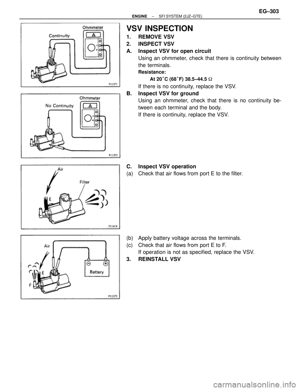
VSV INSPECTION
1. REMOVE VSV
2. INSPECT VSV
A. Inspect VSV for open circuit
Using an ohmmeter, check that there is continuity between
the terminals.
Resistance:
At 20°C (68°F) 38.5±44.5 �
If there is no continuity, replace the VSV.
B. Inspect VSV for ground
Using an ohmmeter, check that there is no continuity be-
tween each terminal and the body.
If there is continuity, replace the VSV.
C. Inspect VSV operation
(a) Check that air flows from port E to the filter.
(b) Apply battery voltage across the terminals.
(c) Check that air flows from port E to F.
If operation is not as specified, replace the VSV.
3. REINSTALL VSV
± ENGINESFI SYSTEM (2JZ±GTE)EG±303
Page 1594 of 2543
VSV FOR WASTE GATE VALVE
COMPONENTS FOR REMOVAL AND
INSTALLATION
VSV INSPECTION
1. REMOVE VSV ASSEMBLY
2. INSPECT VSV
A. Inspect VSV for open circuit
Using an ohmmeter, check that there is continuity between
the terminals.
Resistance:
At 20°C (68°F) 22±26 �
If there is no continuity, replace the VSV.
B. Inspect VSV for ground
Using an ohmmeter, check that there is no continuity be-
tween each terminal and the body.
If there is continuity, replace the VSV. EG±304
± ENGINESFI SYSTEM (2JZ±GTE)
Page 1595 of 2543
C. Inspect VSV operation
(a) Check that air does not flow from port E to F.
(b) Apply battery voltage across the terminals.
(c) Check that air flows from port E to F.
If operation is not as specified, replace the VSV.
3. REINSTALL VSV ASSEMBLY
VSV FOR EXHAUST GAS CONTROL
VA LV E
COMPONENTS FOR REMOVAL AND
INSTALLATION
± ENGINESFI SYSTEM (2JZ±GTE)EG±305
 Using an ohmmeter, check")


 Check that air flows from port E to G.
(b) Apply battery voltage across the terminals.
(c) Check that air flows from port E to the filter.
If operation is not as speci")

 Check that air does not flow from port E to F.
(b) Apply battery voltage across the terminals.
(c) Check that air flows from port E to F.
If operation is not as specif")