Page 1572 of 2543
INJECTORS REPLACEMENT
1. REMOVE INJECTORS
(a) Apply gasoline between the delivery pipe and injectors.
(b) Using SST, lift up the 6 injectors.
SST 09268±74010
(c) Remove the insulator and 2 O±rings from each injector.
2. REINSTALL INJECTORS
(a) Apply a light coat of gasoline to 2 new O±rings.
(b) Install the 2 O±rings and new insulator to each injector.
(c) Push in the 6 injectors so that the injector connectors are
positioned as shown in the illustration. EG±282
± ENGINESFI SYSTEM (2JZ±GTE)
Page 1573 of 2543
FUEL PRESSURE PULSATION DAMPER
COMPONENTS FOR REMOVAL AND
INSTALLATION
FUEL PRESSURE PULSATION DAMPER
REMOVAL
1. REMOVE STARTER
(See starter removal in Starting System)
2. REMOVE FUEL PRESSURE PULSATION DAMPER
(a) Remove the pulsation damper and upper gasket.
(b) Disconnect the fuel inlet pipe from the fuel pipe support, and
remove the lower gasket.
FUEL PRESSURE PULSATION DAMPER
INSTALLATION
1. INSTALL FUEL PRESSURE PULSATION DAMPER
(a) Install the fuel inlet pipe and pulsation damper with 2 new
gaskets.
HINT: Different sized gaskets are used for the upper (large
size) and lower (small size).
± ENGINESFI SYSTEM (2JZ±GTE)EG±283
Page 1574 of 2543
(b) Using SST, tighten the pulsation damper.
SST 09612±24014 (09617±24011)
Torque:
41 NVm (420 kgfVcm, 30 ftVlbf)
35 NVm (350 kgfVcm, 25 ftVlbf) for SST
HINT: Use a torque wrench with a fulcrum length of 30 cm
(11.81 in.).
2. INSTALL STARTER
(See starter installation in Starting System)
4. CHECK FOR FUEL LEAKS
(See item 5 in fuel system in precaution) EG±284
± ENGINESFI SYSTEM (2JZ±GTE)
Page 1575 of 2543
FUEL TANK AND LINE
COMPONENTS
± ENGINESFI SYSTEM (2JZ±GTE)EG±285
Page 1576 of 2543
PRECAUTIONS
1. Always use new gaskets when replacing the fuel tank or
component parts.
2. Apply the proper torque to all parts tightened.
FUEL LINES AND CONNECTIONS
INSPECTION
(a) Check the fuel lines for cracks or leakage, and all
connections for deformation.
(b) C h e c k t h e f u e l t a n k vapor vent system hoses and
connections for looseness, sharp bends or damage.
(c) Check the fuel tank for deformation, cracks, fuel leakage or
tank band looseness.
(d) Check the filler neck for damage or fuel leakage.
(e) Hose and tube connections are as shown in the illustration.
If a problem is found, repair or replace the part as necessary. EG±286
± ENGINESFI SYSTEM (2JZ±GTE)
Page 1577 of 2543
MAS AIR FLOW (MAF) METER
COMPONENTS FOR REMOVAL AND
INSTALLATION
MAF METER REMOVAL
Installation is in the reverse order of removal.
1. REMOVE NO.1 AIR HOSE
2. REMOVE AIR CLEANER HOSE
3. REMOVE MAF METER
(a) Remove the 2 bolts, and disconnect the MAF meter from the
air cleaner case.
Torque: 6.9 NVm (70 kgfVcm, 61 in.Vlbf)
(b) Disconnect the MAF meter wire from the wire clamp on the
air cleaner case.
(c) Disconnect the MAF meter connector, and remove the MAF
meter.
± ENGINESFI SYSTEM (2JZ±GTE)EG±287
Page 1578 of 2543

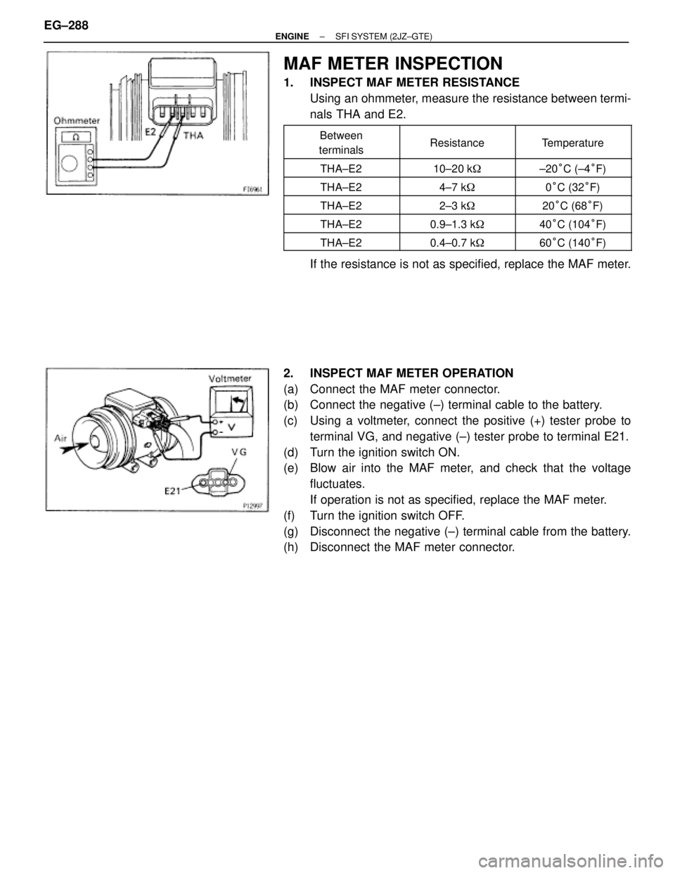
MAF METER INSPECTION
1. INSPECT MAF METER RESISTANCE
Using an ohmmeter, measure the resistance between termi-
nals THA and E2.
�������� �
������� ��������
Between
terminals�������� �
������� ��������Resistance
�������� �
������� ��������Temperature
�������� ��������THA±E2�������� ��������10±20 k��������� ��������±20°C (±4°F)
�������� ��������THA±E2�������� ��������4±7 k��������� ��������0°C (32°F)
�������� ��������THA±E2�������� ��������2±3 k��������� ��������20°C (68°F)�������� ��������THA±E2�������� ��������0.9±1.3 k��������� ��������40°C (104°F)�������� ��������THA±E2�������� ��������0.4±0.7 k��������� ��������60°C (140°F)
If the resistance is not as specified, replace the MAF meter.
2. INSPECT MAF METER OPERATION
(a) Connect the MAF meter connector.
(b) Connect the negative (±) terminal cable to the battery.
(c) Using a voltmeter, connect the positive (+) tester probe to
terminal VG, and negative (±) tester probe to terminal E21.
(d) Turn the ignition switch ON.
(e) Blow air into the MAF meter, and check that the voltage
fluctuates.
If operation is not as specified, replace the MAF meter.
(f) Turn the ignition switch OFF.
(g) Disconnect the negative (±) terminal cable from the battery.
(h) Disconnect the MAF meter connector. EG±288
± ENGINESFI SYSTEM (2JZ±GTE)
Page 1579 of 2543

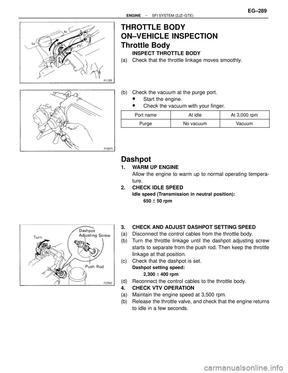
THROTTLE BODY
ON±VEHICLE INSPECTION
Throttle Body
INSPECT THROTTLE BODY
(a) Check that the throttle linkage moves smoothly.
(b) Check the vacuum at the purge port.
wStart the engine.
wCheck the vacuum with your finger.
�������� ��������Port name�������� ��������At idle�������� ��������At 3,000 rpm
�������� ��������Purge�������� ��������No vacuum�������� ��������Vacuum
Dashpot
1. WARM UP ENGINE
Allow the engine to warm up to normal operating tempera-
ture.
2. CHECK IDLE SPEED
Idle speed (Transmission in neutral position):
650
+ 50 rpm
3. CHECK AND ADJUST DASHPOT SETTING SPEED
(a) Disconnect the control cables from the throttle body.
(b) Turn the throttle linkage until the dashpot adjusting screw
starts to separate from the push rod. Then keep the throttle
linkage at that position.
(c) Check that the dashpot is set.
Dashpot setting speed:
2,300 + 400 rpm
(d) Reconnect the control cables to the throttle body.
4. CHECK VTV OPERATION
(a) Maintain the engine speed at 3,500 rpm.
(b) Release the throttle valve, and check that the engine returns
to idle in a few seconds.
± ENGINESFI SYSTEM (2JZ±GTE)EG±289