Page 1818 of 2543
STABILIZER BAR AND LINK REMOVAL
Installation is in the reverse order of removal.
1. REMOVE FRONT WHEELS
Torque: 103 NVm (1,050 kgfVcm, 76 ftVlbf)
2. REMOVE ENGINE UNDER COVER
3. REMOVE BOTH STABILIZER BAR LINKS
Remove the nuts and stabilizer bar links from the stabilizer
bar and the lower suspension arm.
Torque: 74 NVm (750 kgfVcm, 54 ftVlbf)
HINT: If the ball joint stud turns together with the nut, use a
hexagon wrench to hold the stud.
4. REMOVE STABILIZER BAR
(a) Remove the left and right apron seal set bolts.
(b) Remove the 4 bracket bolts and the stabilizer bar with the
cushions and brackets.
Torque: 18 NVm (180 kgfVcm, 13 ftVlbf)
5. REMOVE CUSHIONS AND BRACKETS
INSTALLATION HINT: Install the cushion to the outside of the
line.
± SUSPENSION AND AXLEFRONT SUSPENSIONSA±33
Page 1832 of 2543
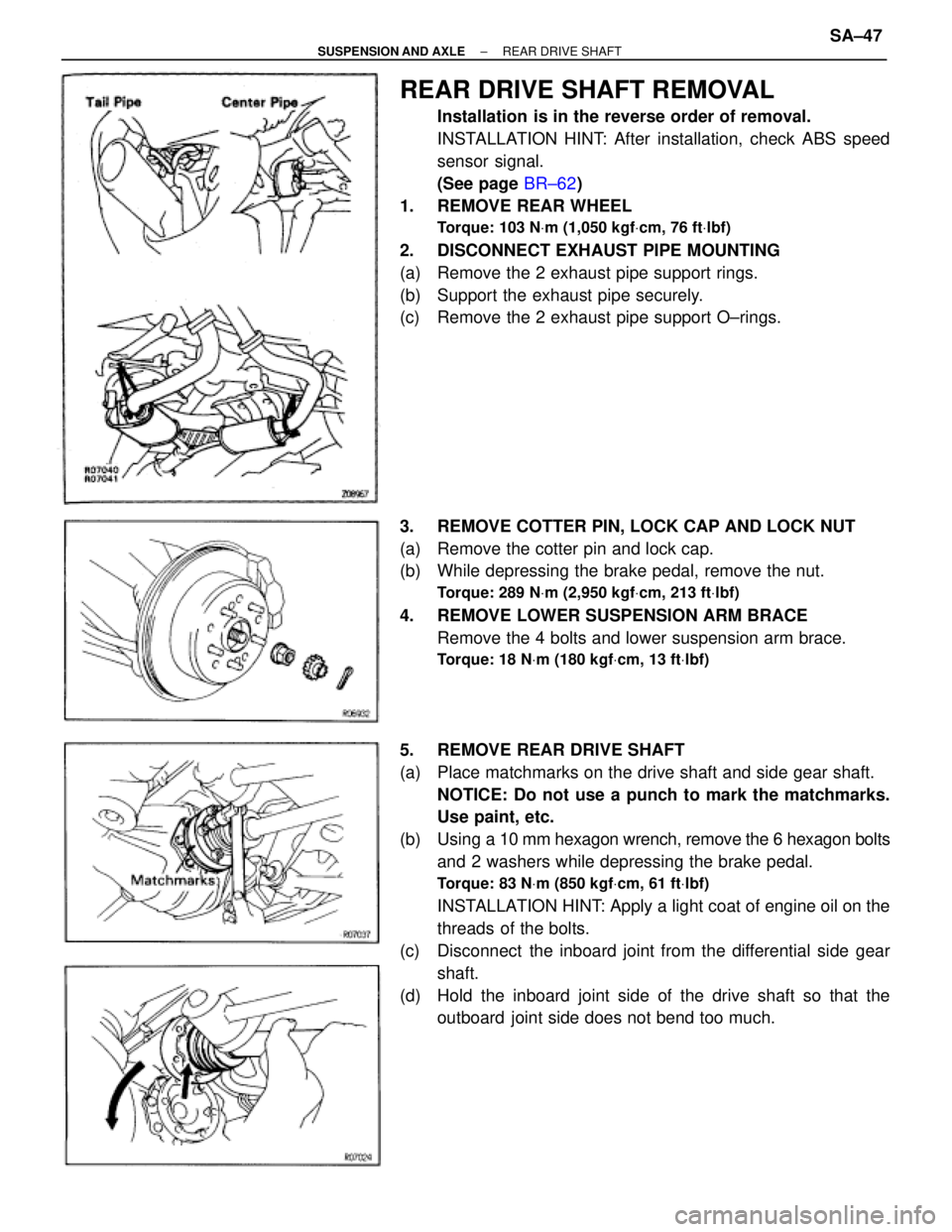
REAR DRIVE SHAFT REMOVAL
Installation is in the reverse order of removal.
INSTALLATION HINT: After installation, check ABS speed
sensor signal.
(See page BR±62)
1. REMOVE REAR WHEEL
Torque: 103 NVm (1,050 kgfVcm, 76 ftVlbf)
2. DISCONNECT EXHAUST PIPE MOUNTING
(a) Remove the 2 exhaust pipe support rings.
(b) Support the exhaust pipe securely.
(c) Remove the 2 exhaust pipe support O±rings.
3. REMOVE COTTER PIN, LOCK CAP AND LOCK NUT
(a) Remove the cotter pin and lock cap.
(b) While depressing the brake pedal, remove the nut.
Torque: 289 NVm (2,950 kgfVcm, 213 ftVlbf)
4. REMOVE LOWER SUSPENSION ARM BRACE
Remove the 4 bolts and lower suspension arm brace.
Torque: 18 NVm (180 kgfVcm, 13 ftVlbf)
5. REMOVE REAR DRIVE SHAFT
(a) Place matchmarks on the drive shaft and side gear shaft.
NOTICE: Do not use a punch to mark the matchmarks.
Use paint, etc.
(b) Using a 10 mm hexagon wrench, remove the 6 hexagon bolts
and 2 washers while depressing the brake pedal.
Torque: 83 NVm (850 kgfVcm, 61 ftVlbf)
INSTALLATION HINT: Apply a light coat of engine oil on the
threads of the bolts.
(c) Disconnect the inboard joint from the differential side gear
shaft.
(d) Hold the inboard joint side of the drive shaft so that the
outboard joint side does not bend too much.
± SUSPENSION AND AXLEREAR DRIVE SHAFTSA±47
Page 1846 of 2543
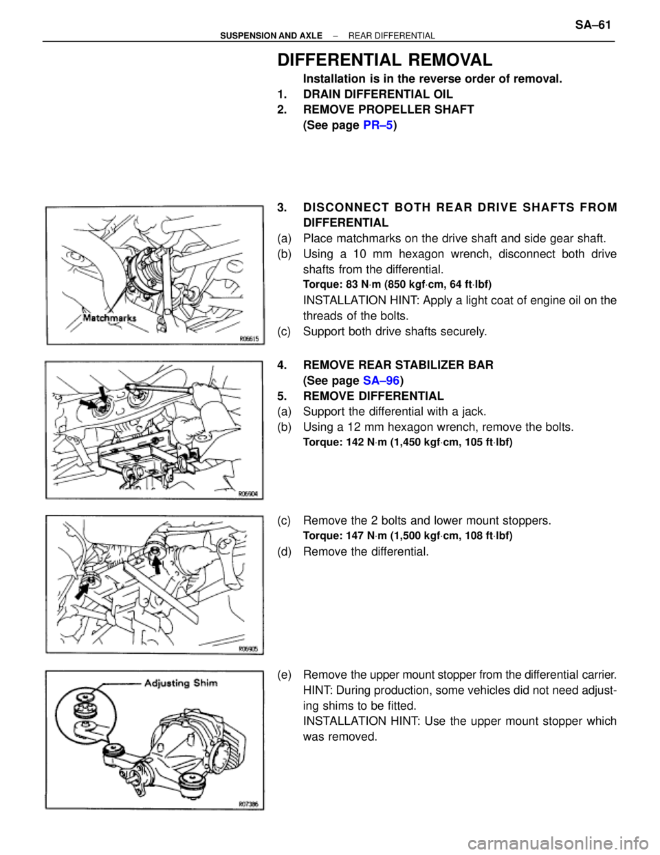
DIFFERENTIAL REMOVAL
Installation is in the reverse order of removal.
1. DRAIN DIFFERENTIAL OIL
2. REMOVE PROPELLER SHAFT
(See page PR±5)
3. DISCONNECT BOTH REAR DRIVE SHAFTS FROM
DIFFERENTIAL
(a) Place matchmarks on the drive shaft and side gear shaft.
(b) Using a 10 mm hexagon wrench, disconnect both drive
shafts from the differential.
Torque: 83 NVm (850 kgfVcm, 64 ftVlbf)
INSTALLATION HINT: Apply a light coat of engine oil on the
threads of the bolts.
(c) Support both drive shafts securely.
4. REMOVE REAR STABILIZER BAR
(See page SA±96)
5. REMOVE DIFFERENTIAL
(a) Support the differential with a jack.
(b) Using a 12 mm hexagon wrench, remove the bolts.
Torque: 142 NVm (1,450 kgfVcm, 105 ftVlbf)
(c) Remove the 2 bolts and lower mount stoppers.
Torque: 147 NVm (1,500 kgfVcm, 108 ftVlbf)
(d) Remove the differential.
(e) Remove the upper mount stopper from the differential carrier.
HINT: During production, some vehicles did not need adjust-
ing shims to be fitted.
INSTALLATION HINT: Use the upper mount stopper which
was removed.
± SUSPENSION AND AXLEREAR DIFFERENTIALSA±61
Page 1889 of 2543
2JZ±GE ENGINE TROUBLESHOOTING
EG±381
Page 1890 of 2543
P. EG±783
P. EG±785, P. EG±387
P. EG±386
P. IN±24
P. EG±386
P. EG±400P. EG±388
P. EG±408
P. EG±409
P. EG±399
Vehicle Brought to Workshop
Customer Problem Analysis
Check and Clear Diagnostic Trouble Code (Precheck)
Setting the Test Mode Diagnosis
Problem Symptom Confirmation
Malfunction does not occur.
Malfunction
occur.Symptom Simulation
Diagnostic Trouble Code Check
Malfunction codeNormal code
Basic Inspection
Matrix chart of Problem Symptoms
Circuit Inspection
Parts Inspection
Confirmation Test
Adjustment, Repair
Identification of Problem
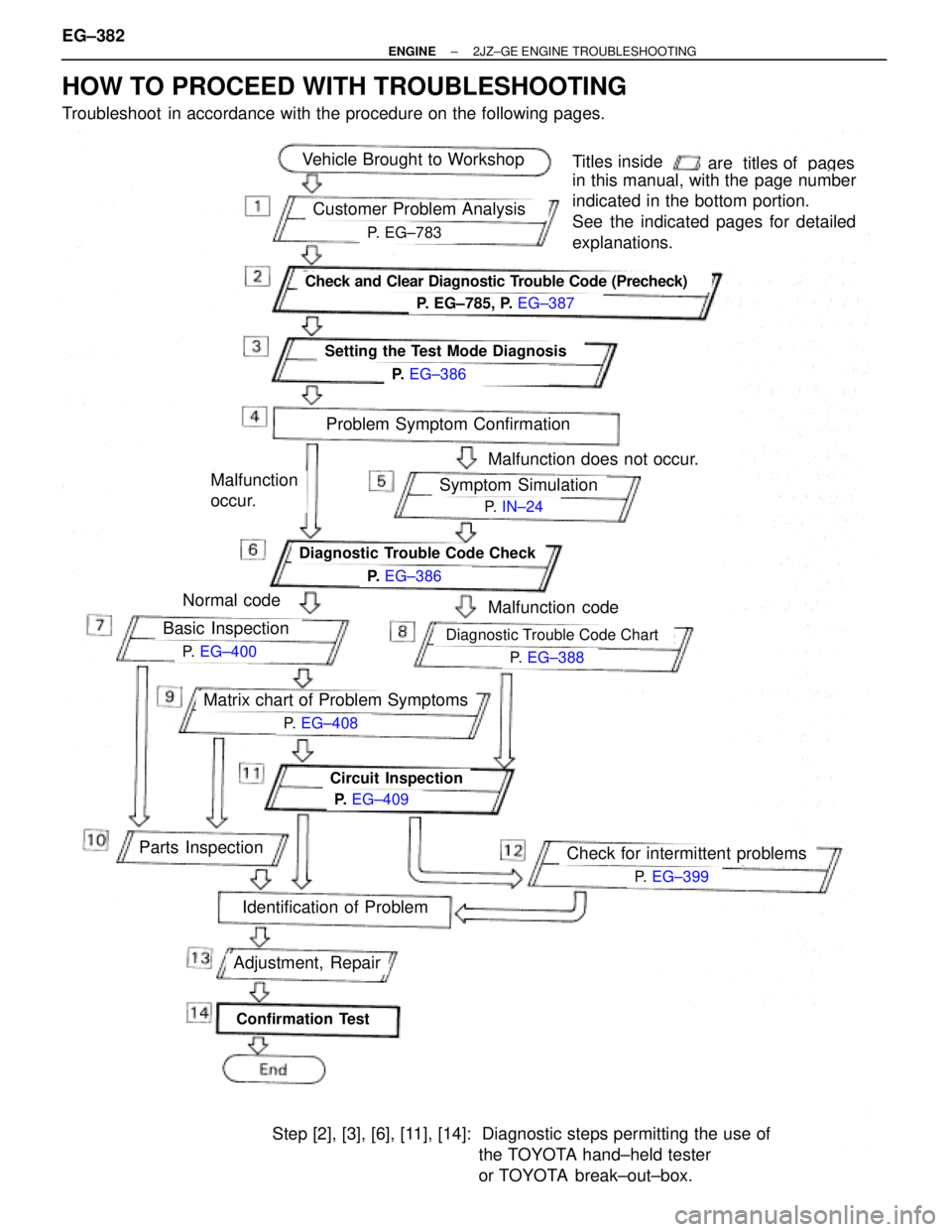
Step [2], [3], [6], [11], [14]: Diagnostic steps permitting the use of
the TOYOTA hand±held tester
or TOYOTA break±out±box.
Titles insideare titles of pages
in this manual, with the page number
indicated in the bottom portion.
See the indicated pages for detailed
explanations.
Diagnostic Trouble Code Chart
Check for intermittent problems
HOW TO PROCEED WITH TROUBLESHOOTING
Troubleshoot in accordance with the procedure on the following pages. EG±382
± ENGINE2JZ±GE ENGINE TROUBLESHOOTING
Page 1891 of 2543
CUSTOMER PROBLEM ANALYSIS CHECK SHEET
± ENGINE2JZ±GE ENGINE TROUBLESHOOTINGEG±383
Page 1892 of 2543
DIAGNOSIS SYSTEM
DESCRIPTION
The ECM contains a built±in self±diagnosis system by which
troubles with the engine signal network are detected and a Mal-
function Indicator Lamp on the instrument panel lights up.
By analyzing various signals as shown in a later table (See page
EG±388) the Engine Control Module (ECM) detects system mal-
functions relating to the sensors or actuators.
In the normal mode, the self±diagnosis system monitors 18
(California specification vehicles) or 17 (except for California and
Canadian specification) items, indicated by code No. as shown in
EG±388. A malfunction indicator lamp informs the driver that a
malfunction has been detected. The lamp goes off automatically
when the malfunction has been repaired, but the diagnostic
trouble code(s) remains stored in the ECM memory (except for
code Nos. 16 and 53). The ECM stores the code(s) until it is
cleared by removing the EFI No. 1 fuse with the ignition switch
OFF.
The diagnostic trouble code can be read by the number of blinks
of the malfunction indicator lamp when TE1 and E1 terminals on
the data link connector 1 or 2 are connected. When 2 or more
codes are indicated, the lowest number (code) will appear first.
In the test mode, 12 (California specification vehicles) or 11 (ex-
cept for California and Canadian specification vehicles) items, in-
dicated by code No. as shown in EG±388 are monitored. If a mal-
function is detected in any one of the systems indicated by code
Nos. 13, 21, 22, 24, 25, 26, 27, 28, 35, 41, 71 and 78 (California
specification vehicles) or 13, 21, 22, 24, 25, 28, 35, 41, 71 and 78
(except for California and Canadian specification vehicles) the
ECM lights the malfunction indicator lamp to warn the technician
that a malfunction has been detected. In this case, TE2 and E1
terminals on the data link connector 2 should be connected as
shown later. (See page EG±386).
In the test mode, even if the malfunction is corrected, the malfunc-
tion code is stored in the ECM memory even when the ignition
switch OFF (except code Nos. 43 and 51). This also applies in the
normal mode. The diagnostic trouble mode (normal or test) and
the output of the malfunction indicator lamp can be selected by
connecting the TE1, TE2 and E1 terminals on the data link con-
nector 2, as shown later.
A test mode function has been added to the functions of the self±
diagnosis system of the normal mode for the purpose of detecting
malfunctions such as poor contact, which are difficult to detect in
the normal mode. This function fills up the self±diagnosis system.
The test mode can be implemented by the technician following the
appropriate procedures of check terminal connection and opera-
tion described later. (See page EG±386) EG±384
± ENGINE2JZ±GE ENGINE TROUBLESHOOTING
Page 1893 of 2543
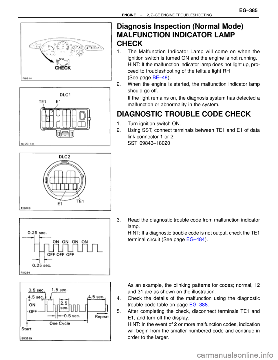
Diagnosis Inspection (Normal Mode)
MALFUNCTION INDICATOR LAMP
CHECK
1. The Malfunction Indicator Lamp will come on when the
ignition switch is turned ON and the engine is not running.
HINT: If the malfunction indicator lamp does not light up, pro-
ceed to troubleshooting of the telltale light RH
(See page BE±48).
2. When the engine is started, the malfunction indicator lamp
should go off.
If the light remains on, the diagnosis system has detected a
malfunction or abnormality in the system.
DIAGNOSTIC TROUBLE CODE CHECK
1. Turn ignition switch ON.
2. Using SST, connect terminals between TE1 and E1 of data
link connector 1 or 2.
SST 09843±18020
3. Read the diagnostic trouble code from malfunction indicator
lamp.
HINT: If a diagnostic trouble code is not output, check the TE1
terminal circuit (See page EG±484).
As an example, the blinking patterns for codes; normal, 12
and 31 are as shown on the illustration.
4. Check the details of the malfunction using the diagnostic
trouble code table on page EG±388.
5. After completing the check, disconnect terminals TE1 and
E1, and turn off the display.
HINT: In the event of 2 or more malfunction codes, indication
will begin from the smaller numbered code and continue in
order to the larger.
± ENGINE2JZ±GE ENGINE TROUBLESHOOTINGEG±385