Page 1918 of 2543
INSPECTION PROCEDURE
Check resistance of each pickup coils in distributor.
INSPECTION USING OSCILLOSCOPE
Replace Distributor
Repair or replace harness or connector
Check for open and short in harness and connector between engine control
module and distributor (See page IN±30).
Disconnect distributor connector.
Measure resistance between each terminal shown
in the table below.
ªColdº is from Ð 10°C (14°F) to 50°C (122°F)
and ªHotº is from 50°C (122°F) to 100°C
(212°F).
wDuring cranking or idling, check waveforms between
terminals G1, G2, NE and G � of engine control
module
HINT: The correct waveforms are as shown.
G1 pickup coil
G2 pickup coil
NE pickup coil
(NE±G �)
(G1±G �)
(G2±G �)
Resistance
EG±410± ENGINE2JZ±GE ENGINE TROUBLESHOOTING
Page 1919 of 2543
Check air gap.
Remove distributor cap & rotor.
Using SST (G1 and G2 pickups) and a thickness gauge
(NE pickup), measure the air gap between the signal ro-
tor and pickup coil projection.
SST 09240±00020 for G1 and G2 pickups
Air gap: 0.2 Ð 0.5 mm (0.008 Ð 0.020 in.)
Replace distributor housing assembly
Check and replace engine control module.
± ENGINE2JZ±GE ENGINE TROUBLESHOOTINGEG±411
Page 1920 of 2543

DTC 13 G NE Signal Circuit (No.2)
CIRCUIT DESCRIPTION
See G, NE signal circuit (No. 1) on page EG±409.
����� �����DTC No.���������������� ����������������Diagnostic Trouble Code Detecting Condition����������������� �����������������Trouble Area����� �
���� �����
13
���������������� �
��������������� ���������������� No NE signal to ECM for 0.1 sec. or more at
1,000 rpm or more����������������� �
���������������� ������������������ Open or short in NE circuit
�Distributor����� �
���� �
���� �����
13���������������� �
��������������� �
��������������� ����������������
NE signal does not pulse 12 times to ECM
during the interval between G1 and G2 pulses
����������������� �
���������������� �
���������������� �����������������
� Distributor
� ECM
DIAGNOSIS
This code indicates that a intermittent problems of the G, NE signal from the distributor to the ECM has occurred,
but that it has returned to normal. Note that although this problem may not necessarily appear at the time of
inspection, it cannot be ignored because this diagnostic trouble code is output, indicating that there is or was
a malfunction in the G, NE signal circuit; this ºmalfunctionº is usually a loose connector.
The distributor connector and the NE terminal of the ECM connector must therefore be checked for the following:
1. Loose connectors
2. Dirty connector terminals
3. Loose connector terminals EG±412
± ENGINE2JZ±GE ENGINE TROUBLESHOOTING
Page 1921 of 2543

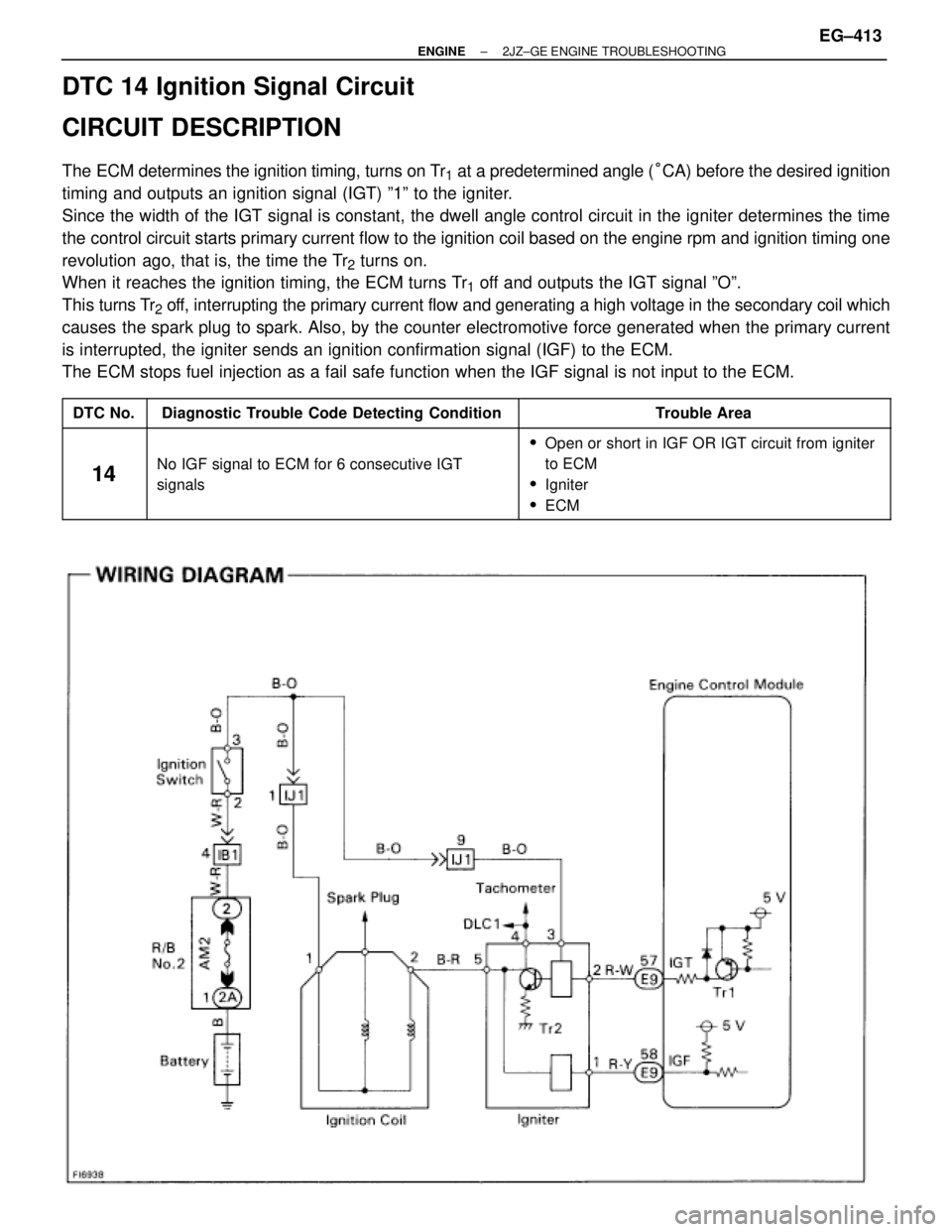
DTC 14 Ignition Signal Circuit
CIRCUIT DESCRIPTION
The ECM determines the ignition timing, turns on Tr1 at a predetermined angle (°CA) before the desired ignition
timing and outputs an ignition signal (IGT) º1º to the igniter.
Since the width of the IGT signal is constant, the dwell angle control circuit in the igniter determines the time
the control circuit starts primary current flow to the ignition coil based on the engine rpm and ignition timing one
revolution ago, that is, the time the Tr
2 turns on.
When it reaches the ignition timing, the ECM turns Tr
1 off and outputs the IGT signal ºOº.
This turns Tr
2 off, interrupting the primary current flow and generating a high voltage in the secondary coil which
causes the spark plug to spark. Also, by the counter electromotive force generated when the primary current
is interrupted, the igniter sends an ignition confirmation signal (IGF) to the ECM.
The ECM stops fuel injection as a fail safe function when the IGF signal is not input to the ECM.
����� �����DTC No.���������������� ����������������Diagnostic Trouble Code Detecting Condition����������������� �����������������Trouble Area����� �
���� �����
14
���������������� �
��������������� ���������������� No IGF signal to ECM for 6 consecutive IGT
����������������� �
���������������� ������������������Open or short in IGF OR IGT circuit from igniter
to ECM
����� �
���� �����
14���������������� �
��������������� ����������������
No IGF signal to ECM for 6 consecutive IGT
signals����������������� �
���������������� �����������������
to ECM
�Igniter
�ECM
± ENGINE2JZ±GE ENGINE TROUBLESHOOTINGEG±413
Page 1922 of 2543

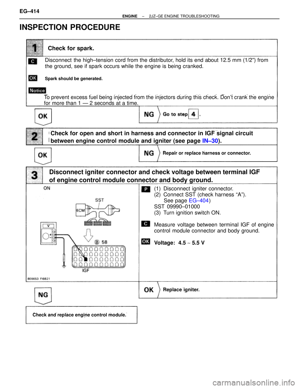
INSPECTION PROCEDURE
(See page IN±30).
(See page EG±404)
Check for spark.
Disconnect the high±tension cord from the distributor, hold its end about 12.5 mm (1/2º) from
the ground, see if spark occurs while the engine is being cranked.
Spark should be generated.
To prevent excess fuel being injected from the injectors during this check. Don't crank the engine
for more than 1 Ð 2 seconds at a time.
Check for open and short in harness and connector in IGF signal circuit
between engine control module and igniter (see page IN±30).
Disconnect igniter connector and check voltage between terminal IGF
of engine control module connector and body ground.
Repair or replace harness or connector.
Replace igniter.
Check and replace engine control module.
(1) Disconnect igniter connector.
(2) Connect SST (check harness ªAº).
See page EG±404)
SST 09990±01000
(3) Turn ignition switch ON.
Measure voltage between terminal IGF of engine
control module connector and body ground.
Voltage: 4.5 ~ 5.5 V EG±414
± ENGINE2JZ±GE ENGINE TROUBLESHOOTING
Page 1923 of 2543
Connect SST (check harness ªAº).
See page EG±404)
SST 09990±01000
Measure voltage between terminal IGF of engine
control module connector and body ground when
engine is cranked.
Voltage: 0.5 Ð 1.0 V
(Neither 0 V nor 5 V)
Check voltage between terminal IGT of engine control module connector and
body ground.
INSPECTION USING OSCILLOSCOPE
�During cranking or idling, check waveforms between
terminal IGT and E1 of engine control module.
HINT: The correct rectangular waveforms are as shown.
Check voltage between terminal 3 of igniter connector and body ground.
Disconnect igniter connector.
Measure voltage between terminal 3 of igniter
connector and body ground, when ignition switch
is turned to ªONº and ªSTARTº position.
Voltage: 9 Ð 14 V
Check and repair igniter power source circuit.
± ENGINE2JZ±GE ENGINE TROUBLESHOOTINGEG±415
Page 1924 of 2543
Check ignition coil.
Disconnect ignition coil connector.
(1) Check primary coil.
Measure resistance between terminals of ignition coil
connector.
(2) Check secondary coil.
Measure resistance between terminal � of ignition coil
connector and high±tension terminal.
Repair or replace harness or connector.
Check for open and short in harness and connector between ignitioin switch
and ignition coil, ignition coil and igniter (See page
IN±30).
ªColdº is from Ð 10°C (14°F) to 50°C (122°F) and
ªHotº is from 50°C (122°F) to 100°C (212°F).
Replace ignition coil.
Replace igniter.
Resistance
Primary Coil
Secondary
Coil
EG±416± ENGINE2JZ±GE ENGINE TROUBLESHOOTING
Page 1925 of 2543
Disconnect igniter connector and check voltage between terminal IGT of engine
control module connector and body ground.
Check for open and short in harness and connector in IGT signal circuit be-
tween engine control module and igniter (See page
IN±30).
Replace igniter.
Repair or replace harness or connector.
Check and replace engine control module.
Disconnect igniter connector.
Measure voltage between terminal IGT of engine
control module connector and body ground when
engine is cranked.
Voltage: 0.5 Ð 1.0 V
(Neither 0 V nor 5 V)
�During cranking or idling, check waveforms between
terminal IGT and E1 of engine control module.
HINT: The correct rectangular waveforms are as shown.
INSPECTION USING OSCILLOSCOPE
± ENGINE2JZ±GE ENGINE TROUBLESHOOTINGEG±417