Page 1677 of 2543
2. INSTALL RACK HOUSING BRACKET AND GROMMET
Torque the 2 bolts and nuts.
Torque: 75 NVm (770 kgfVcm, 55 ftVlbf)
3. CONNECT PPS SOLENOID CONNECTOR
4. CONNECT PRESSURE FEED TUBE
Torque the union bolt over a new gasket.
Torque: 49 NVm (500 kgfVcm, 36 ftVlbf)
5. CONNECT RETURN TUBE
Torque the union bolt over 2 new gaskets.
Torque: 49 NVm (500 kgfVcm, 36 ftVlbf)
6. CONNECT RH AND LH TIE ROD ENDS
(See page SA±17)
7. CONNECT INTERMEDIATE SHAFT
(See page SR±21)
8. INSTALL FR SUSPENSION MEMBER PROTECTOR
Torque the 4 bolts.
9. INSTALL ENGINE UNDER COVER
Install the 10 screws.
10. BLEED POWER STEERING SYSTEM
(See page SR±9)
11. CHECK FRONT WHEEL ALIGNMENT
(See page SA±4) SR±46
± STEERINGPOWER STEERING GEAR
Page 1681 of 2543
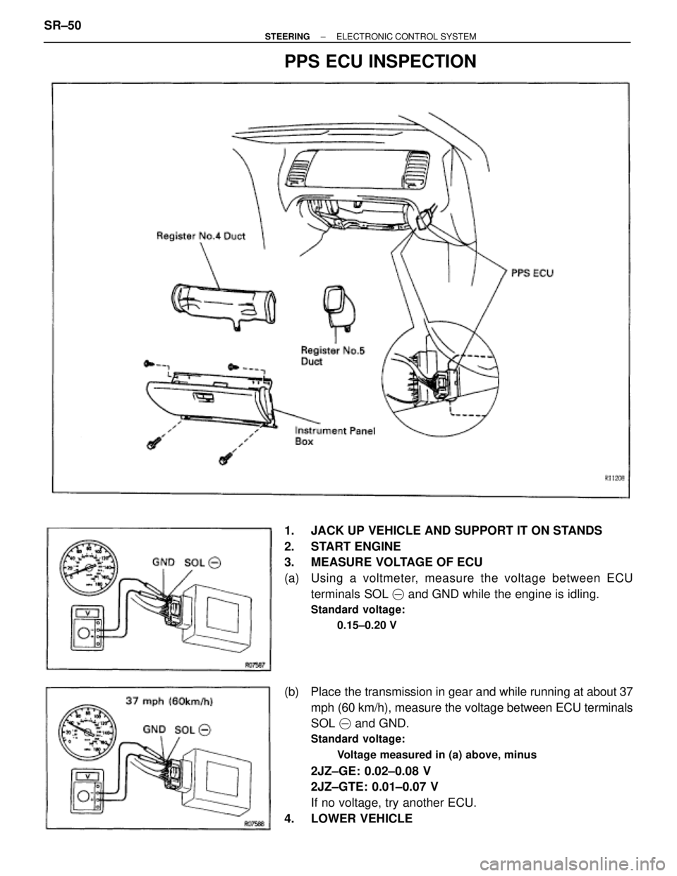
PPS ECU INSPECTION
1. JACK UP VEHICLE AND SUPPORT IT ON STANDS
2. START ENGINE
3. MEASURE VOLTAGE OF ECU
(a) Using a voltmeter, measure the voltage between ECU
terminals SOL � and GND while the engine is idling.
Standard voltage:
0.15±0.20 V
(b) Place the transmission in gear and while running at about 37
mph (60 km/h), measure the voltage between ECU terminals
SOL � and GND.
Standard voltage:
Voltage measured in (a) above, minus
2JZ±GE: 0.02±0.08 V
2JZ±GTE: 0.01±0.07 V
If no voltage, try another ECU.
4. LOWER VEHICLE SR±50
± STEERINGELECTRONIC CONTROL SYSTEM
Page 1731 of 2543
 Does the wire harness connecting with its corresponding
part have insufficient slack?
(b) Are the term")
CONNECTORS
Slightly shake the connector vertically and horizontally.
Inspection of connectors
(a) Does the wire harness connecting with its corresponding
part have insufficient slack?
(b) Are the terminals dirty?
(c) Are the terminals making loose contact due to terminals
spread?
WIRE HARNESS
Slightly shake the wire harness vertically and horizontally.
Thoroughly check the connector joint, the fulcrum of the
vibration and the wiring opening in the engine/passenger
compartment panel.
PARTS AND SENSORS
Gently tap the part or sensor considered to be the problem
caused and check if the malfunction will occur.
CAUTION: Do not apply vibration to the center airbag
sensor assembly.
VIBRATION METHOD: When vibration seems to be the major cause.
SYMPTOM SIMULATION
ªIntermittent troubles or problemsº are the malfunctions about which the customer has a complaint, but which
do not occur and cannot be confirmed in the workshop. The intermittent problems also include complaints about
the SRS warning light going on and off erratically.
The self±diagnostic system stores the circuit of the intermittent problem in memory even if the ignition switch
is turned off.
For accurate diagnosis of the problems, ask the customer to obtain as much information as possible following
the customer problem analysis check sheet (See page RS±43) and try to reproduce the intermittent problem.
The problem simulation methods described below are the effective ways to reproduce the problem conditions
by applying vibration, heat, and humidity. RS±48
± SUPPLEMENTAL RESTRAINT SYSTEMTROUBLESHOOTING
Page 1736 of 2543
![TOYOTA SUPRA 1995 Service Repair Manual INSPECTION PROCEDURES [P] Preparation [C] Check
(1) Turn ignition switch to LOCK.
(2) Disconnect center airbag sensor assembly con±
nector.
(3) Turn ignition swit](/manual-img/14/57468/w960_57468-1735.png "TOYOTA SUPRA 1995 Service Repair Manual INSPECTION PROCEDURES [P] Preparation [C] Check
(1) Turn ignition switch to LOCK.
(2) Disconnect center airbag sensor assembly con±
nector.
(3) Turn ignition swit")
INSPECTION PROCEDURES [P] Preparation [C] Check
(1) Turn ignition switch to LOCK.
(2) Disconnect center airbag sensor assembly con±
nector.
(3) Turn ignition switch ON. But do not start engine.
(4) Measure voltage at IG
2 or ACC on connector
wire harness side of center airbag sensor as±
sembly and operate electric system (defogger,
wiper, headlight, heater blower, etc.).
Voltage: 6 V Ð 11.5 V at IG
2 and ACC.
(5) Turn electric system switch OFF.
(6) Turn ignition switch to LOCK.
(7) Remove voltmeter and connect center sensor
assembly connector.
Preparation.
Does SRS warning light turn off?
Turn ignition switch ON.
Operate electric system checked in [1] (4) and
check that SRA warning light goes off.
Turn ignition switch ON.
Check battery and charging system.
(See charging system section)
Check diagnostic trouble code, and if a malfunc-
tion code is output, perform troubleshooting ac-
cording to malfunction code. If a normal code is
output, replace center airbag sensor assembly.
± SUPPLEMENTAL RESTRAINT SYSTEMTROUBLESHOOTINGRS±53
Page 1789 of 2543

WHEEL ALIGNMENT
FRONT WHEEL ALIGNMENT
1. MEASURE VEHICLE HEIGHT
Front vehicle height
�������� ��������Engine�������� ��������Tire size�������� ��������Height
�������� ��������2JZ±GE�������� ��������225/50ZR16�������� ��������185 mm (7.28 in.)
�������� ��������2JZ±GTE�������� ��������235/45ZR17�������� ��������187 mm (7.36 in.)
Measuring point:
Measure from the ground to the center of the lower suspen-
sion arm front mounting bolt.
NOTICE: Before inspecting the wheel alignment, adjust
the vehicle height to specification.
If the vehicle height is not to specification, try to adjust it by
pushing down on or lifting the body.
2. INSTALL CAMBER±CASTER±KINGPIN GAUGE OR
ONTO WHEEL ALIGNMENT TESTER
Follow the specific instructions of the equipment manufactur-
er.
3. INSPECT CAMBER, CASTER AND STEERING AXIS
INCLINATION
Specifications
�������� ���������������� ��������2JZ±GE�������� ��������2JZ±GTE
�������� �
������� ��������
Camber
Left±right error�������� �
������� ��������
±0°20'+45'
30' or less�������� �
������� ��������
±0°30'+45'
30' or less
�������� �
������� ��������
Caster
Left±right error�������� �
������� ��������
3°20'+45'
30' or less�������� �
������� ��������
3°30'+45'
30' or less
�������� �
������� ��������
Steering axis
inclination�������� �
������� ��������
9°35'+45'
(Reference)�������� �
������� ��������
9°45'+45'
(Reference)
If the steering axis inclination is not as specified, after camber
and caster have been correctly adjusted, recheck the steer-
ing knuckle front wheel for bearing or looseness.
4. INSPECT TOE±IN
Toe±in (total):
A+B: 0° + 0.2°
C±D: 0 + 2 mm (0 + 0.08 in.)
If toe±in is not within specification adjust by the tie rod end. SA±4
± SUSPENSION AND AXLEWHEEL ALIGNMENT
Page 1790 of 2543
 Remove the engine under cover.
(b) Remove the nut, 2 bolts and front lower arm bracket stay.
(c) Loosen the front and/or rear adjusting cam nuts.
(d) Adjust the ca")
5. ADJUST CAMBER AND CASTER
(a) Remove the engine under cover.
(b) Remove the nut, 2 bolts and front lower arm bracket stay.
(c) Loosen the front and/or rear adjusting cam nuts.
(d) Adjust the camber and caster by front and/or rear adjusting
cams. (See adjustment chart)
Specifications
�������� ���������������� ��������2JZ±GE�������� ��������2JZ±GTE
�������� ��������Camber
Left±right error�������� ��������±0°20' + 30'
30' or less�������� ��������±0°30' + 30'
30' or less
�������� �
������� ��������Caster
Left±right error�������� �
������� ��������3°20' + 30'
30' or less�������� �
������� ��������3°30' + 30'
30' or less
(e) Torque the front and/or rear adjusting cam nuts.
Torque: 226 NVm (2,300 kgfVcm, 166 ftVlbf)
(f) Install the front lower arm bracket stay.
Torque:
Nut: 43 NVm (440 kgfVcm, 32 ftVlbf)
Bolt: 59 NVm (600 kgfVcm, 43 ftVlbf)
(g) Install the engine under cover.
6. ADJUST TOE±IN
(a) Remove the boot clamps.
(b) Loosen the tie rod end lock nuts.
(c) Turn the left and right tie rod ends an amount to adjust the
toe±in.
Toe±in (total):
A+ B: 0° + 0.1°
C±D: 0 + 1 mm (0 + 0.04 in.)
HINT: Ensure that the lengths of the left and right tie rods are
the same.
Tie rod end length left±right error:
Less than 1.5 mm (0.059 in.)
(d) Tighten the tie rod end lock nut.
Torque: 56 NVm (570 kgfVcm, 41 ftVlbf)
(e) Place the boot on the seat and clip it.
HINT: Ensure that the boots are not twisted.
± SUSPENSION AND AXLEWHEEL ALIGNMENTSA±5
Page 1794 of 2543

REAR WHEEL ALIGNMENT
1. MEASURE VEHICLE HEIGHT
Rear vehicle height
�������� ��������Engine�������� ��������Tire size�������� ��������Height
�������� ��������2JZ±GE�������� ��������245/50ZR16�������� ��������250 mm (9.84 in.)
�������� ��������2JZ±GTE�������� ��������255/40ZR17�������� ��������251 mm (9.88 in.)
Measuring point:
Measure from the ground to the center of the lower suspen-
sion arm No.2 mounting bolt.
NOTICE: Before inspecting the wheel alignment, adjust
the vehicle height to specification.
If the vehicle height is not to specification, try to adjust it by
pushing down on or lifting the body.
2. INSTALL CAMBER±CASTER±KINGPIN GAUGE OR
ONTO WHEEL ALIGNMENT TESTER
Follow the specific instructions of the equipment manufactur-
er.
3. INSPECT CAMBER
�������� �
������� ��������
�������� �
������� ��������2JZ±GE�������� �
������� ��������2JZ±GTE�������� �
������� ��������Camber
�������� �
������� ��������±1°35' + 45'
�������� �
������� ��������±1°30' + 45'
�������� ��������Left±right error�������� ��������30' or less�������� ��������30' or less
4. INSPECT TOE±IN
Toe±in (total):
A+ B: 0.3° + 0.2°
C±D: 3 + 2 mm (0.12 + 0.08 in.)
5. ADJUST CAMBER AND TOE±IN
(a) Measure the length of the lower suspension arm No.1 and
No.2, as shown in the illustration.
Length:
(E±F) or (F±E) should be less 4.0 mm.
If not, adjust the length of the arms by turning the adjusting
cam, as shown, until (E±F) or (F±E) is less than 4.0 mm.
(b) Measure the camber and toe±in.
Specifications
����������� �
���������� �����������Toe±in������������ �
����������� ������������ A+ B: 0.3° + 0.1°
C±D: 3 + 1 mm (0.12 + 0.04 in.)
����������� �
���������� ����������� Camber (2JZ±GE)
Left±right error������������ �
����������� ������������±1°35' + 30'
30' or less
����������� �
���������� ����������� Camber (2JZ±GTE)
Left±right error������������ �
����������� ������������±1°30' + 30'
30' or less
If the camber and toe±in are still not within the specification,
adjust the camber and toe±in with the adjusting cam.
± SUSPENSION AND AXLEWHEEL ALIGNMENTSA±9
Page 1815 of 2543

1. REMOVE FRONT WHEEL
Torque: 103 NV")
LOWER SUSPENSION ARM REMOVAL
Installation is in the reverse order of removal.
INSTALLATION HINT: After installation, check front wheel
alignment.
(See page SA±4)
1. REMOVE FRONT WHEEL
Torque: 103 NVm (1,050 kgfVcm, 76 ftVlbf)
2. REMOVE ENGINE UNDER COVER
3. REMOVE BRAKE CALIPER
(a) Remove the 2 bolts and brake caliper from the steering
knuckle.
Torque: 118 NVm (1,200 kgfVcm, 87 ftVlbf)
(b) Support the brake caliper securely.
4. DISCONNECT STABILIZER BAR LINK FROM LOWER
SUSPENSION ARM
Remove the nut and disconnect the link from the arm.
Torque: 74 NVm (750 kgfVcm, 54 ftVlbf)
HINT: If the ball joint stud turns together with the nut, use a
hexagon wrench to hold the stud.
5. DISCONNECT STEERING KNUCKLE
(a) Remove the clip and nut.
Torque: 125 NVm (1,270 kgfVcm, 92 ftVlbf)
(b) Using SST, disconnect the steering knuckle from the lower
suspension arm.
SST 09628±62011
6. REMOVE LOWER SUSPENSION ARM
(a) Remove the bolt, nut and disconnect the lower suspension
arm from the shock absorber.
Torque: 143 NVm (1,460 kgfVcm, 106 ftVlbf)
INSTALLATION HINT: After stabilizing the suspension,
torque the nut. SA±30
± SUSPENSION AND AXLEFRONT SUSPENSION

3. CONNECT PPS SOLENOID CONNECTOR
4. CONNECT PRESSURE FEED TUBE
Torque the union bolt")