Page 1216 of 2248
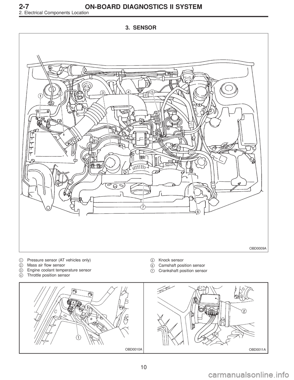
3. SENSOR
OBD0009A
�1Pressure sensor (AT vehicles only)
�
2Mass air flow sensor
�
3Engine coolant temperature sensor
�
4Throttle position sensor�
5Knock sensor
�
6Camshaft position sensor
�
7Crankshaft position sensor
OBD0010AOBD0011A
10
2-7ON-BOARD DIAGNOSTICS II SYSTEM
2. Electrical Components Location
Page 1218 of 2248
OBD0017A
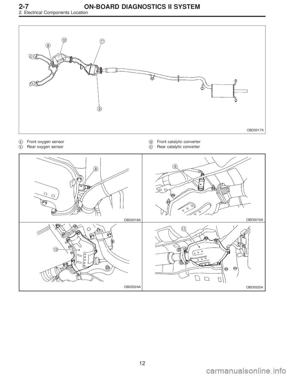
�8Front oxygen sensor
�
9Rear oxygen sensor�
10Front catalytic converter
�
11Rear catalytic converter
OBD0018AOBD0019A
OBD0524AOBD0525A
12
2-7ON-BOARD DIAGNOSTICS II SYSTEM
2. Electrical Components Location
Page 1229 of 2248
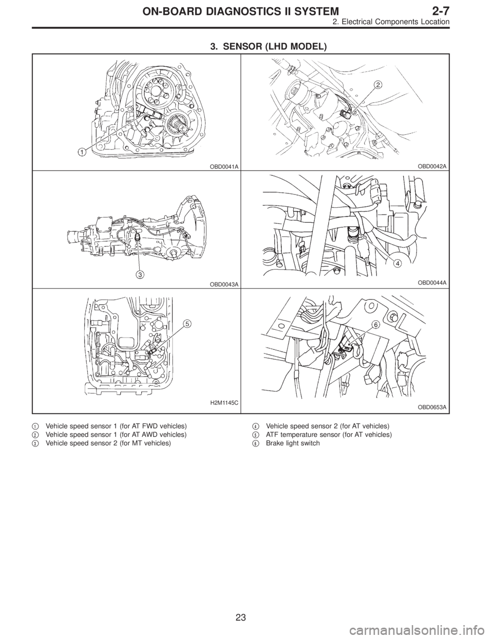
3. SENSOR (LHD MODEL)
OBD0041AOBD0042A
OBD0043AOBD0044A
H2M1145COBD0653A
�1Vehicle speed sensor 1 (for AT FWD vehicles)
�
2Vehicle speed sensor 1 (for AT AWD vehicles)
�
3Vehicle speed sensor 2 (for MT vehicles)�
4Vehicle speed sensor 2 (for AT vehicles)
�
5ATF temperature sensor (for AT vehicles)
�
6Brake light switch
23
2-7ON-BOARD DIAGNOSTICS II SYSTEM
2. Electrical Components Location
Page 1230 of 2248
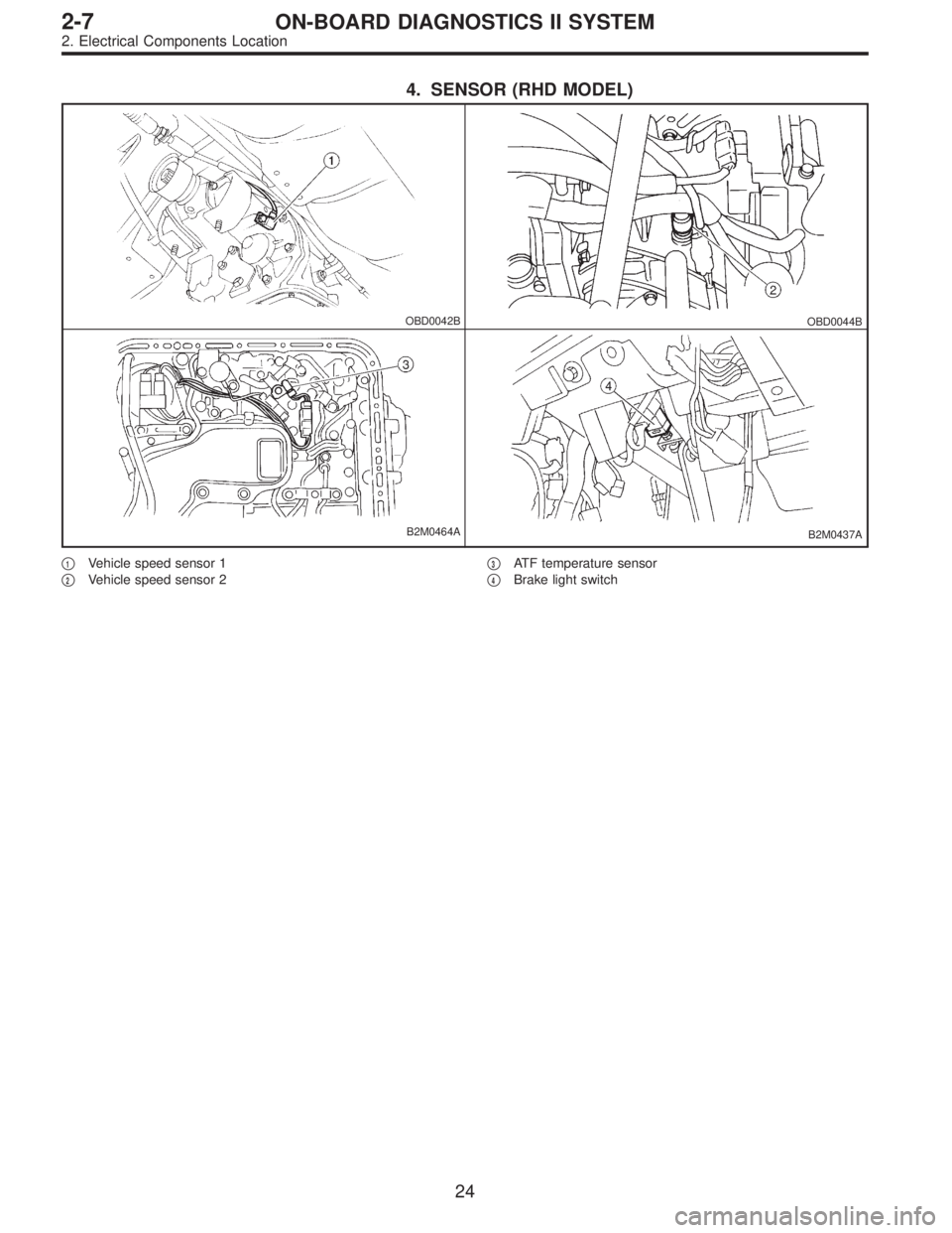
4. SENSOR (RHD MODEL)
OBD0042BOBD0044B
B2M0464AB2M0437A
�1Vehicle speed sensor 1
�
2Vehicle speed sensor 2�
3ATF temperature sensor
�
4Brake light switch
24
2-7ON-BOARD DIAGNOSTICS II SYSTEM
2. Electrical Components Location
Page 1234 of 2248
 Prepare a general scan tool (OBD-II general scan tool)
required by SAE J1978.
2) Open the cover and connect the OBD-II ge")
OBD0006C
B: OBD-II GENERAL SCAN TOOL
1. HOW TO USE OBD-II GENERAL SCAN TOOL
1) Prepare a general scan tool (OBD-II general scan tool)
required by SAE J1978.
2) Open the cover and connect the OBD-II general scan
tool to the data link connector located in the lower portion
of the instrument panel (on the driver’s side), to the lower
cover.
3) Using the OBD-II general scan tool, call up diagnostic
trouble code(s) and freeze frame data.
OBD-II general scan tool functions consist of:
(1) MODE $01: Current powertrain diagnostic data
(2) MODE $02: Powertrain freeze frame data
(3) MODE $03: Emission-related powertrain diagnostic
trouble codes
(4) MODE $04: Clear/Reset emission-related diagnos-
tic information
(5) MODE $05: Oxygen sensor monitoring test results
Read out data according to repair procedures.
(For detailed operation procedures, refer to the OBD-II
General Scan Tool Operation Manual.)
NOTE:
For details concerning diagnostic trouble codes, refer to
the DIAGNOSTIC TROUBLE CODE (DTC) LIST [T11A0].
H2M1280
2. DATA LINK CONNECTOR (FOR OBD-II GENERAL
SCAN TOOL AND SUBARU SELECT MONITOR)
1) This connector is used both for OBD-II general scan
tools and Subaru Select Monitor.
2) Terminal No. 4 to No. 6 of data link connector is used
for Subaru Select Monitor signal.
CAUTION:
Do not connect scan tools other than OBD-II general
scan tools and Subaru Select Monitor, because the
circuit for Subaru Select Monitor may be damaged.
Terminal No. Contents Terminal No. Contents
1 Power supply 9 Blank
2 Blank10 K line of ISO 9141 CARB
3 Blank11 Blank
4 Subaru Select Monitor signal (ECM to Subaru Select monitor)* 12 Ground
5 Subaru Select Monitor signal (Subaru Select monitor to ECM)* 13 Ground
6 Subaru Select Monitor clock* 14 Blank
7 Blank15 Blank
8 Blank16 Blank
*: Circuit only for Subaru Select Monitor
28
2-7ON-BOARD DIAGNOSTICS II SYSTEM
3. Diagnosis System
Page 1235 of 2248

3. READ DATA LIST
�MODE $01
—Current powertrain diagnostic data—
Refers to data denoting the current operating condition of
analog input/output, digital input/output and/or the power-
train system.
A list of the support data and PID (Parameter Identification)
codes are shown in the following table.
PID DataUnit of measure
01 Number of emission-related powertrain trouble codes and MIL status ON/OFF
03 Fuel system control status—
04 Calculated engine load value%
05 Engine coolant temperature°C
06 Short term fuel trim%
07 Long term fuel trim%
0B Intake manifold absolute pressurekPa
0C Engine revolutionrpm
0D Vehicle speedkm/h
0E Ignition timing advance°
10 Air flow rate from mass air flow sensor g/sec
11 Throttle valve opening angle%
13 Check whether oxygen sensor is installed.—
14 Oxygen sensor output voltage and short term fuel trim associated with oxygen sensor—bank 1 V and %
15 Oxygen sensor output voltage and short term fuel trim associated with oxygen sensor—bank 2 V and %
1C On-board diagnosis system—
NOTE:
Refer to OBD-II general scan tool manufacturer’s instruc-
tion manual to access generic OBD-II PIDs (MODE $01).
29
2-7ON-BOARD DIAGNOSTICS II SYSTEM
3. Diagnosis System
Page 1237 of 2248
.
NOTE:
R")
�MODE $04
—Clear/Reset emission-related diagnostic information—
Refers to the mode used to clear or reset emission-related
diagnostic information (OBD-II trouble diagnostic informa-
tion).
NOTE:
Refer to OBD-II general scan tool manufacturer’s instruc-
tion manual to clear or reset emission-related diagnostic
information (MODE $04).
�MODE $05
—Oxygen sensor monitoring test results—
Refers to the mode using oxygen sensor output data while
the on-board diagnosis system is performing diagnosis on
the oxygen sensor.
A list of the support oxygen sensor output data and test ID
(identification) are shown in the following table.
Test ID DataUnit of measure
01 Rich to lean sensor threshold voltage (constant) V
02 Lean to rich sensor threshold voltage (constant) V
03 Low sensor voltage for switch time calculation (constant) V
04 High sensor voltage for switch time calculation (constant) V
05 Rich to lean sensor switch time (calculated) sec.
06 Lean to rich sensor switch time (calculated) sec.
07 Minimum sensor voltage for test cycle (calculated) V
08 Maximum sensor voltage for test cycle (calculated) V
NOTE:
Refer to OBD-II general scan tool manufacturer’s instruc-
tion manual to access oxygen sensor monitoring test
results (MODE $05).
31
2-7ON-BOARD DIAGNOSTICS II SYSTEM
3. Diagnosis System
Page 1241 of 2248

2. READ DATA FUNCTION KEY LIST FOR ENGINE
Function mode Contents Abbreviation Unit of measure
F00 ROM ID number YEAR—
F01 Battery voltage VB V
F02 Vehicle speed signal VSP m/h
F03 Vehicle speed signal VSP km/h
F04 Engine speed signal EREV rpm
F05 Engine coolant temperature signal TW°F
F06 Engine coolant temperature signal TW°C
F07 Ignition signal ADVS deg
F08 Mass air flow signal QA V
F09 Load data DATA—
F10 Throttle position signal THV V
F11 Injector pulse width TIM mS
F12 Idle air control signal ISC %
F13 Front oxygen sensor output signal FO2 V
F14 Front oxygen sensor maximum output signal FO2max V
F15 Front oxygen sensor minimum output signal FO2min V
F16 Rear oxygen sensor output signal RO2 V
F17 Rear oxygen sensor maximum output signal RO2max V
F18 Rear oxygen sensor minimum output signal RO2min V
F19 Short term fuel trim ALPHA %
F20 Knock sensor signal RTRD deg
F21 A/F correction (short term trim) by rear oxygen sensor PHOS %
F23 Atmospheric absolute pressure signal (AT vehicles) BARO. P V
F24 Intake manifold absolute pressure signal (AT vehicles) MANI. P V
F25 Long term fuel trim KBLRC %
F28 Long term whole fuel trim K0 %
F29 Front oxygen sensor heater current FO2H A
F30 Rear oxygen sensor heater current RO2H A
F33Maximum value of cylinder #1 misfire times during 200
rotationsMF1 %
F34Maximum value of cylinder #2 misfire times during 200
rotationsMF2 %
F35Maximum value of cylinder #3 misfire times during 200
rotationsMF3 %
F36Maximum value of cylinder #4 misfire times during 200
rotationsMF4 %
F37 Maximum EGR system pressure value (AT vehicles) EGRmax mmHg
F38 Minimum EGR system pressure value (AT vehicles) EGRmin mmHg
F45 Load data LOAD %
F46 Throttle position signal THV %
F47 Mass air flow signal QA g/s
F48 Atmospheric absolute pressure signal BARO. P kPa
F49 Intake manifold absolute pressure signal MANI. P kPa
35
2-7ON-BOARD DIAGNOSTICS II SYSTEM
3. Diagnosis System