Page 728 of 2248
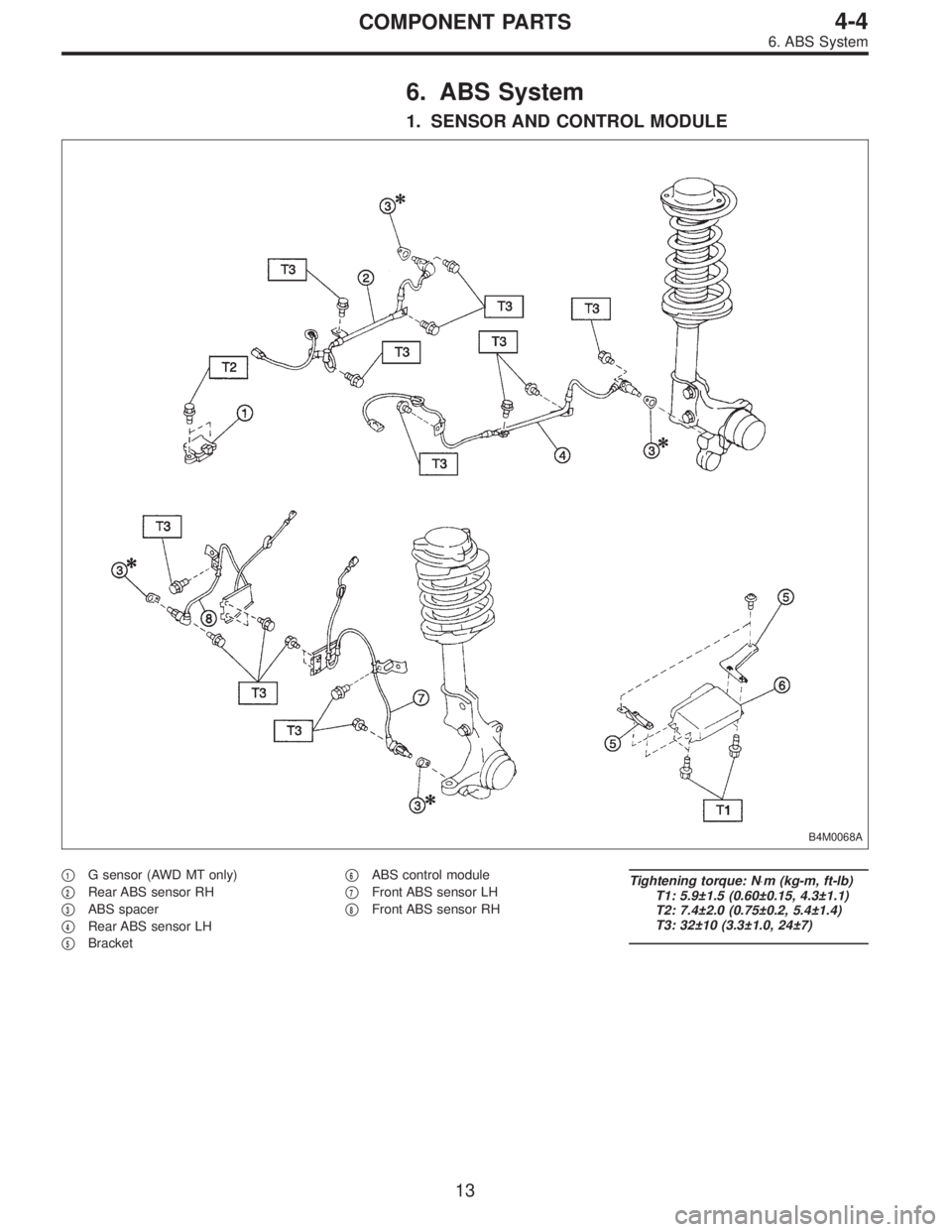
6. ABS System
1. SENSOR AND CONTROL MODULE
B4M0068A
�1G sensor (AWD MT only)
�
2Rear ABS sensor RH
�
3ABS spacer
�
4Rear ABS sensor LH
�
5Bracket�
6ABS control module
�
7Front ABS sensor LH
�
8Front ABS sensor RH
Tightening torque: N⋅m (kg-m, ft-lb)
T1: 5.9±1.5 (0.60±0.15, 4.3±1.1)
T2: 7.4±2.0 (0.75±0.2, 5.4±1.4)
T3: 32±10 (3.3±1.0, 24±7)
13
4-4COMPONENT PARTS
6. ABS System
Page 732 of 2248
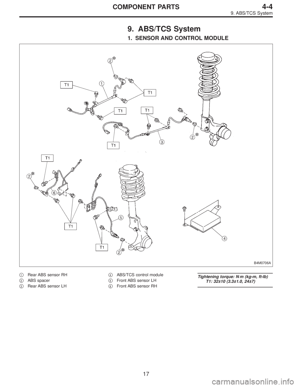
9. ABS/TCS System
1. SENSOR AND CONTROL MODULE
B4M0706A
�1Rear ABS sensor RH
�
2ABS spacer
�
3Rear ABS sensor LH�
4ABS/TCS control module
�
5Front ABS sensor LH
�
6Front ABS sensor RH
Tightening torque: N⋅m (kg-m, ft-lb)
T1: 32±10 (3.3±1.0, 24±7)
17
4-4COMPONENT PARTS
9. ABS/TCS System
Page 777 of 2248
14. ABS Sensor
A: REMOVAL
1. FRONT ABS SENSOR
1) Disconnect front ABS sensor connector located in
engine compartment.
B4M0079A
2) Remove bolts which secure sensor harness to strut.
G4M0451
3) Remove bolts which secure sensor harness to body.
G4M0443
4) Remove bolts which secure front ABS sensor to
housing, and remove front ABS sensor.
CAUTION:
�Be careful not to damage pole piece located at tip of
the sensor and teeth faces during removal.
�Do not pull sensor harness during removal.
5) Remove front disc brake caliper and disc rotor from
housing after removing front tire.
6) Remove front drive shaft and housing and hub assem-
bly.
60
4-4SERVICE PROCEDURE
14. ABS Sensor
Page 778 of 2248
G4M0444
7) Remove tone wheel while removing hub from housing
and hub assembly.
CAUTION:
Be careful not to damage teeth faces of tone wheel
during removal.
2. REAR ABS SENSOR
1) Remove rear seat and disconnect rear ABS sensor con-
nector.
2) Remove rear sensor harness bracket from rear trailing
link and bracket.
G4M0445
3) Remove rear ABS sensor from rear back plate.
4) Remove rear tone wheel while removing hub from
housing and hub assembly.
CAUTION:
�Be careful not to damage pole piece located at tip of
the sensor and teeth faces during removal.
�Do not pull sensor harness during removal.
B: INSPECTION
1. ABS SENSOR
1) Check pole piece of ABS sensor for foreign particles or
damage. If necessary, clean pole piece or replace ABS
sensor.
61
4-4SERVICE PROCEDURE
14. ABS Sensor
Page 779 of 2248
B4M0248
2) Measure ABS sensor resistance.
ABS sensor Terminal No. Standard
Front - LH 1 and 2
1.0±0.2 kΩ Front - RH 1 and 2
Rear - LH 1 and 2
Rear - RH 1 and 2
CAUTION:
If resistance is outside the standard value, replace
ABS sensor with new one.
NOTE:
Check ABS sensor cable for discontinuity. If necessary,
replace with a new one.
G4M0448
2. TONE WHEEL
1) Check tone wheel’s teeth (44 pieces) for cracks or
dents. If necessary, replace tone wheel with a new one.
2) Clearances (sensor gaps) should be measured one by
one to ensure tone wheel and speed sensor are installed
correctly.
ABS sensor clearance:
Front
0.9—1.4 mm (0.035—0.055 in)
Rear
0.7—1.2 mm (0.028—0.047 in)
NOTE:
�If clearance is narrow, adjust by using spacer (Part No.
26755AA000).
�If clearance is wide, check the outputted voltage then
replace ABS sensor or tone wheel if the outputted voltage
is outside the specification.
62
4-4SERVICE PROCEDURE
14. ABS Sensor
Page 780 of 2248
B4M0118B
3. OUTPUT VOLTAGE
Output voltage can be checked by the following method.
Install resistor and condenser, then rotate wheel about 2.75
km/h (2 MPH) or equivalent.
NOTE:
Regarding terminal No., please refer to item 1. ABS SEN-
SOR.
C: INSTALLATION
1. FRONT ABS SENSOR
1) Install tone wheel on hub, then install housing on hub
assembly.
G4M0443
2) Temporarily install front ABS sensor on housing.
CAUTION:
Be careful not to strike ABS sensor’s pole piece and
tone wheel’s teeth against adjacent metal parts during
installation.
3) Install front drive shaft to hub spline.
[W1E0].>
63
4-4SERVICE PROCEDURE
14. ABS Sensor
Page 781 of 2248
G4M0451
4) Install front ABS sensor on strut and wheel apron
bracket.
Tightening torque:
32±10 N⋅m (3.3±1.0 kg-m, 24±7 ft-lb)
5) Place a thickness gauge between ABS sensor’s pole
piece and tone wheel’s tooth face. After standard clearance
is obtained over the entire perimeter, tighten ABS sensor
on housing to specified torque.
ABS sensor standard clearance:
0.9—1.4 mm (0.035—0.055 in)
Tightening torque:
32±10 N⋅m (3.3±1.0 kg-m, 24±7 ft-lb)
CAUTION:
Check the marks on the harness to make sure that no
distortion exists. (RH: white, LH: yellow)
NOTE:
If the clearance is outside specifications, readjust.
2. REAR ABS SENSOR
1) Install rear tone wheel on hub, then rear housing on
hub.
G4M0445
2) Temporarily install rear ABS sensor on back plate.
CAUTION:
Be careful not to strike ABS sensor’s pole piece and
tone wheel’s teeth against adjacent metal parts during
installation.
64
4-4SERVICE PROCEDURE
14. ABS Sensor
Page 782 of 2248
3) Install rear drive shaft to rear housing and rear differen-
tial spindle.
G4M0453
4) Install rear sensor harness on rear trailing link.
Tightening torque:
32±10 N⋅m (3.3±1.0 kg-m, 24±7 ft-lb)
5) Place a thickness gauge between ABS sensor’s pole
piece and tone wheel’s tooth face. After standard clearance
is obtained over the entire perimeter, tighten ABS sensor
on back plate to specified torque.
ABS sensor standard clearance:
0.7—1.2 mm (0.028—0.047 in)
Tightening torque:
32±10 N⋅m (3.3±1.0 kg-m, 24±7 ft-lb)
CAUTION:
Check the marks on the harness to make sure that no
distortion exists. (RH: white, LH: yellow)
NOTE:
If the clearance is outside specifications, readjust.
65
4-4SERVICE PROCEDURE
14. ABS Sensor
 Disconnect front ABS sensor connector located in
engine compartment.
B4M0079A
2) Remove bolts which secure sensor harness to strut.
G4M0451
3) Remove b")
![SUBARU LEGACY 1995 Service Repair Manual G4M0444
7) Remove tone wheel while removing hub from housing
and hub assembly. <Ref. to 4-2 [W1B0].>
CAUTION:
Be careful not to damage teeth faces of tone wheel
during removal.
2. REAR ABS SENSOR
1) R](/manual-img/17/57432/w960_57432-777.png "SUBARU LEGACY 1995 Service Repair Manual G4M0444
7) Remove tone wheel while removing hub from housing
and hub assembly. <Ref. to 4-2 [W1B0].>
CAUTION:
Be careful not to damage teeth faces of tone wheel
during removal.
2. REAR ABS SENSOR
1) R")
 Measure ABS sensor resistance.
ABS sensor Terminal No. Standard
Front - LH 1 and 2
1.0±0.2 kΩ Front - RH 1 and 2
Rear - LH 1 and 2
Rear - RH 1 and 2
CAUTION:
If resistance is outside the")
 or equivalent.
NOTE:
Regarding terminal No.,")
 Install front ABS sensor on strut and wheel apron
bracket.
Tightening torque:
32±10 N⋅m (3.3±1.0 kg-m, 24±7 ft-lb)
5) Place a thickness gauge between ABS sensor’s pole
piece and tone")
![SUBARU LEGACY 1995 Service Repair Manual 3) Install rear drive shaft to rear housing and rear differen-
tial spindle. <Ref. to 4-2 [W2E0].>
G4M0453
4) Install rear sensor harness on rear trailing link.
Tightening torque:
32±10 N⋅m (3.3±1](/manual-img/17/57432/w960_57432-781.png "SUBARU LEGACY 1995 Service Repair Manual 3) Install rear drive shaft to rear housing and rear differen-
tial spindle. <Ref. to 4-2 [W2E0].>
G4M0453
4) Install rear sensor harness on rear trailing link.
Tightening torque:
32±10 N⋅m (3.3±1")