Page 792 of 2248
 Connect connector to ABS control module.
2) Install AB")
B: INSPECTION
Check that connector is connected correctly and that con-
nector terminal sliding resistance is correct.
G4M0469
C: INSTALLATION
1) Connect connector to ABS control module.
2) Install ABS control module on the body.
G4M0470
17. G Sensor for ABS System
A: REMOVAL AND INSTALLATION
The G sensor is located on the right front wheel apron.
G4M0471
B: INSPECTION
1) Check to ensure that G sensor is securely installed on
front wheel apron, and that connector is properly installed.
2) Disconnect connector from G sensor and measure con-
tact resistance between terminals.
Condition of G sensor Standard
On flat surface 610±60Ω
* When slanting about
14°—21.3°(θ)610±60Ω,
More than 100 kΩ
NOTE:
�Tilt G sensor forward as shown in Figure. If it is tilted
backward, it will not operate.
�Hysteresis occurs during ON-OFF operation of sensor.
Sensor should turn OFF from ON (610Ω,More than 100
kΩ) when it is tilted in a range from 14°to 21.3°.
Tightening torque:
7.4±2.0 N⋅m (0.75±0.2 kg-m, 5.4±1.4 ft-lb)
74
4-4SERVICE PROCEDURE
16. ABS Control Module - 17. G Sensor for ABS System
Page 793 of 2248
 Connect connector to ABS control module.
2) Install AB")
B: INSPECTION
Check that connector is connected correctly and that con-
nector terminal sliding resistance is correct.
G4M0469
C: INSTALLATION
1) Connect connector to ABS control module.
2) Install ABS control module on the body.
G4M0470
17. G Sensor for ABS System
A: REMOVAL AND INSTALLATION
The G sensor is located on the right front wheel apron.
G4M0471
B: INSPECTION
1) Check to ensure that G sensor is securely installed on
front wheel apron, and that connector is properly installed.
2) Disconnect connector from G sensor and measure con-
tact resistance between terminals.
Condition of G sensor Standard
On flat surface 610±60Ω
* When slanting about
14°—21.3°(θ)610±60Ω,
More than 100 kΩ
NOTE:
�Tilt G sensor forward as shown in Figure. If it is tilted
backward, it will not operate.
�Hysteresis occurs during ON-OFF operation of sensor.
Sensor should turn OFF from ON (610Ω,More than 100
kΩ) when it is tilted in a range from 14°to 21.3°.
Tightening torque:
7.4±2.0 N⋅m (0.75±0.2 kg-m, 5.4±1.4 ft-lb)
74
4-4SERVICE PROCEDURE
16. ABS Control Module - 17. G Sensor for ABS System
Page 825 of 2248
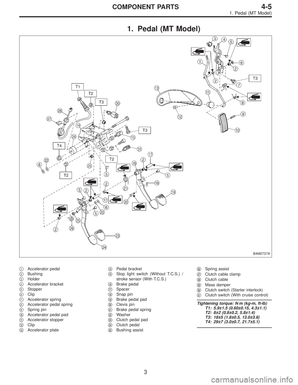
1. Pedal (MT Model)
B4M0737A
�1Accelerator pedal
�
2Bushing
�
3Holder
�
4Accelerator bracket
�
5Stopper
�
6Clip
�
7Accelerator spring
�
8Accelerator pedal spring
�
9Spring pin
�
10Accelerator pedal pad
�
11Accelerator stopper
�
12Clip
�
13Accelerator plate�
14Pedal bracket
�
15Stop light switch (Without T.C.S.) /
stroke sensor (With T.C.S.)
�
16Brake pedal
�
17Spacer
�
18Snap pin
�
19Brake pedal pad
�
20Clevis pin
�
21Brake pedal spring
�
22Washer
�
23Clutch pedal pad
�
24Clutch pedal
�
25Bushing assist�
26Spring assist
�
27Clutch cable clamp
�
28Clutch cable
�
29Mass damper
�
30Clutch switch (Starter interlock)
�
31Clutch switch (With cruise control)
Tightening torque: N⋅m (kg-m, ft-lb)
T1: 5.9±1.5 (0.60±0.15, 4.3±1.1)
T2: 8±2 (0.8±0.2, 5.8±1.4)
T3: 18±5 (1.8±0.5, 13.0±3.6)
T4: 29±7 (3.0±0.7, 21.7±5.1)
3
4-5COMPONENT PARTS
1. Pedal (MT Model)
Page 826 of 2248
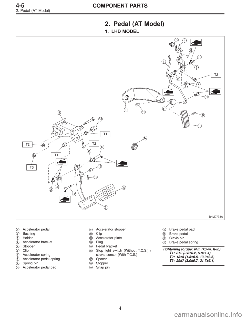
2. Pedal (AT Model)
1. LHD MODEL
B4M0738A
�1Accelerator pedal
�
2Bushing
�
3Holder
�
4Accelerator bracket
�
5Stopper
�
6Clip
�
7Accelerator spring
�
8Accelerator pedal spring
�
9Spring pin
�
10Accelerator pedal pad�
11Accelerator stopper
�
12Clip
�
13Accelerator plate
�
14Plug
�
15Pedal bracket
�
16Stop light switch (Without T.C.S.) /
stroke sensor (With T.C.S.)
�
17Spacer
�
18Stopper
�
19Snap pin�
20Brake pedal pad
�
21Brake pedal
�
22Clevis pin
�
23Brake pedal spring
Tightening torque: N⋅m (kg-m, ft-lb)
T1: 8±2 (0.8±0.2, 5.8±1.4)
T2: 18±5 (1.8±0.5, 13.0±3.6)
T3: 29±7 (3.0±0.7, 21.7±5.1)
4
4-5COMPONENT PARTS
2. Pedal (AT Model)
Page 1028 of 2248

2. WAGON MODEL
Installation is in the reverse order of removal.
CAUTION:
�Do not allow center seat belt to get under cushion
when folding cushion.
�Ensure that side seat belt tongue is free from cush-
ion and trim panel.
�Lift front of cushion to ensure that cushion is prop-
erly locked.
B5M0038A
3. Front Seat Belt
A: REMOVAL AND INSTALLATION
1. OUTER BELT
1) Remove through anchor cover cap.
2) Remove shoulder anchor bolt.
3) Remove side sill rear upper cover and front pillar lower
trim.
4) Remove center pillar lower trim.
B5M0039
5) Remove webbing guide.
6) Roll up floor mat at the bottom of center pillar.
7) Remove lap anchor bolt.
8) Remove outer belt assembly.
G5M0356
2. INNER BELT
Remove anchor nut.
G5M0357
3. ADJUSTABLE SHOULDER ANCHOR
1) Remove shoulder anchor bolt.
2) Remove lower center pillar trim.
3) Remove front and center pillar upper trim.
4) Remove adjustable shoulder anchor assembly.
5) Installation is in the reverse order of removal.
CAUTION:
�The left and right ELR’s are not mutually inter-
changeable because different sensors are used.
�Be careful not to twist belts during installation.
11
5-3SERVICE PROCEDURE
2. Rear Seat - 3. Front Seat Belt
Page 1029 of 2248

2. WAGON MODEL
Installation is in the reverse order of removal.
CAUTION:
�Do not allow center seat belt to get under cushion
when folding cushion.
�Ensure that side seat belt tongue is free from cush-
ion and trim panel.
�Lift front of cushion to ensure that cushion is prop-
erly locked.
B5M0038A
3. Front Seat Belt
A: REMOVAL AND INSTALLATION
1. OUTER BELT
1) Remove through anchor cover cap.
2) Remove shoulder anchor bolt.
3) Remove side sill rear upper cover and front pillar lower
trim.
4) Remove center pillar lower trim.
B5M0039
5) Remove webbing guide.
6) Roll up floor mat at the bottom of center pillar.
7) Remove lap anchor bolt.
8) Remove outer belt assembly.
G5M0356
2. INNER BELT
Remove anchor nut.
G5M0357
3. ADJUSTABLE SHOULDER ANCHOR
1) Remove shoulder anchor bolt.
2) Remove lower center pillar trim.
3) Remove front and center pillar upper trim.
4) Remove adjustable shoulder anchor assembly.
5) Installation is in the reverse order of removal.
CAUTION:
�The left and right ELR’s are not mutually inter-
changeable because different sensors are used.
�Be careful not to twist belts during installation.
11
5-3SERVICE PROCEDURE
2. Rear Seat - 3. Front Seat Belt
Page 1033 of 2248
![SUBARU LEGACY 1995 Service Repair Manual B5M0048A
3. CENTER PILLAR UPPER
<Ref. to 5-3 [C500].>
1) Remove front pillar upper trim.
2) Remove upper anchor of front seat belt.
3) Remove center pillar upper trim panel.
4) Installation is in the](/manual-img/17/57432/w960_57432-1032.png "SUBARU LEGACY 1995 Service Repair Manual B5M0048A
3. CENTER PILLAR UPPER
<Ref. to 5-3 [C500].>
1) Remove front pillar upper trim.
2) Remove upper anchor of front seat belt.
3) Remove center pillar upper trim panel.
4) Installation is in the")
B5M0048A
3. CENTER PILLAR UPPER
1) Remove front pillar upper trim.
2) Remove upper anchor of front seat belt.
3) Remove center pillar upper trim panel.
4) Installation is in the reverse order of removal.
CAUTION:
�The left and right ELR’s are not mutually inter-
changeable because different sensors are used.
�Be careful not to twist belts during installation.
G5M0363
4. FRONT PILLAR UPPER
Remove front pillar upper trim panel.
CAUTION:
Be sure to securely hook pawls of front pillar upper
trim panel on body flange.
B5M0043A
5. REAR PILLAR UPPER
1) Remove rear seat cushion and backrest.
2) Remove rear seat belt. (Lower anchor bolt)
3) Remove rear pillar upper trim panel.
[C500].>
4) Installation is in the reverse order of removal.
CAUTION:
Be sure to securely hook pawls of rear pillar upper trim
panel on body flange.
B5M0049
6. REAR PILLAR LOWER
1) Remove side sill rear upper cover trim.
2) Remove rear pillar lower trim.
B5M0044A
7. REAR QUARTER PILLAR UPPER
1) Remove rear seat belt. (Upper anchor bolt)
2) Remove cap strut.
3) Remove rear quarter upper front trim�
1.
4) Remove rear quarter upper rear trim�
2.
5) Installation is in the reverse order of removal.
CAUTION:
Be sure to securely hook pawls of rear quarter pillar
trim panel on body flange.
14
5-3SERVICE PROCEDURE
5. Inner Trim Panel
Page 1043 of 2248
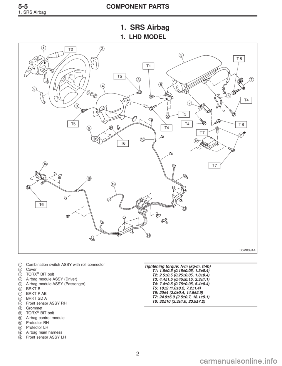
1. SRS Airbag
1. LHD MODEL
B5M0394A
�1Combination switch ASSY with roll connector
�
2Cover
�
3TORX®BIT bolt
�
4Airbag module ASSY (Driver)
�
5Airbag module ASSY (Passenger)
�
6BRKT B
�
7BRKT P AB
�
8BRKT SD A
�
9Front sensor ASSY RH
�
10Grommet
�
11TORX®BIT bolt
�
12Airbag control module
�
13Protector RH
�
14Protector LH
�
15Airbag main harness
�
16Front sensor ASSY LH
Tightening torque: N⋅m (kg-m, ft-lb)
T1: 1.8±0.5 (0.18±0.05, 1.3±0.4)
T2: 2.5±0.5 (0.25±0.05, 1.8±0.4)
T3: 4.4±1.5 (0.45±0.15, 3.3±1.1)
T4: 7.4±0.5 (0.75±0.05, 5.4±0.4)
T5: 10±2 (1.0±0.2, 7.2±1.4)
T6: 20±4 (2.0±0.4, 14.5±2.9)
T7: 24.5±6.9 (2.5±0.7, 18.1±5.1)
T8: 32±10 (3.3±1.0, 23.9±7.2)
2
5-5COMPONENT PARTS
1. SRS Airbag