Page 1762 of 2248
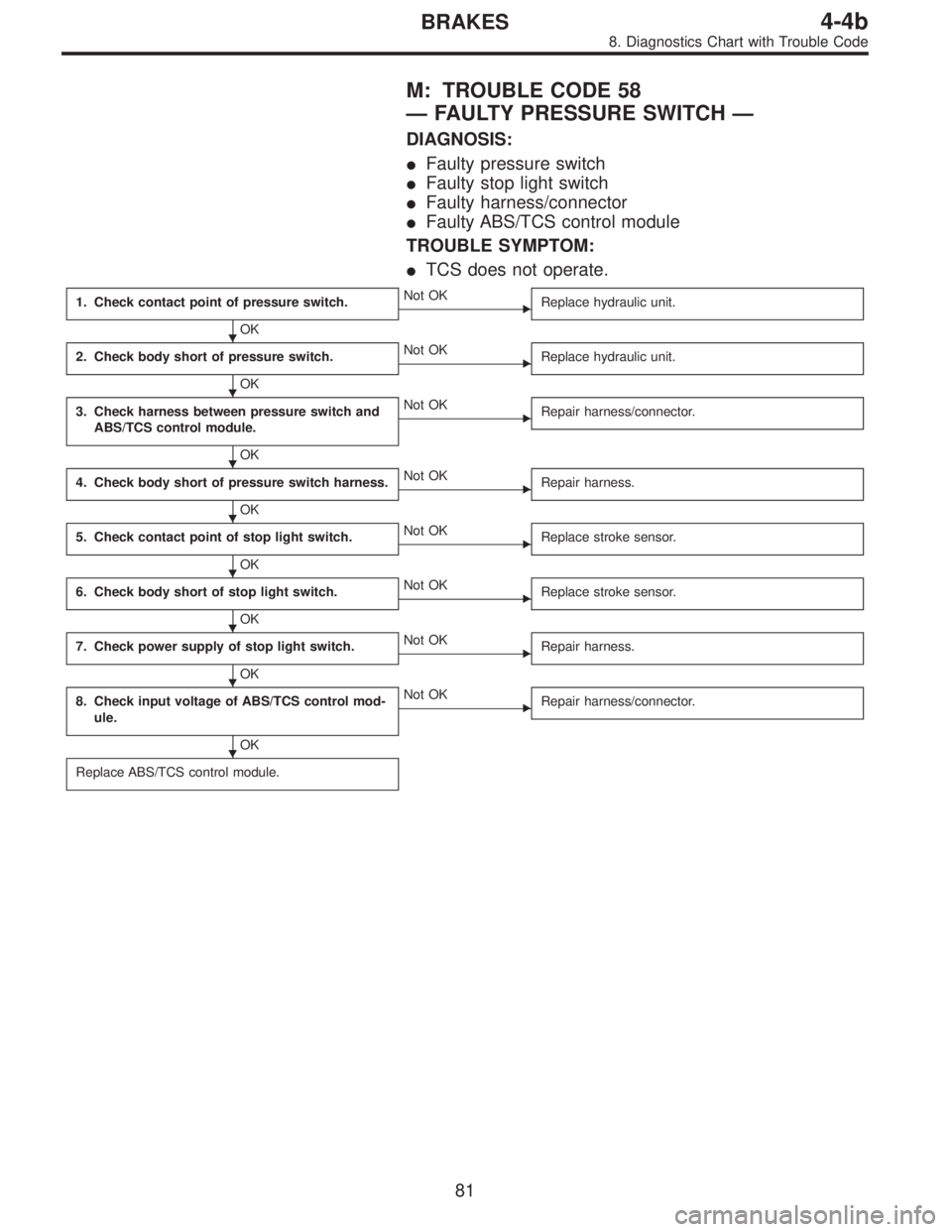
M: TROUBLE CODE 58
—FAULTY PRESSURE SWITCH—
DIAGNOSIS:
�Faulty pressure switch
�Faulty stop light switch
�Faulty harness/connector
�Faulty ABS/TCS control module
TROUBLE SYMPTOM:
�TCS does not operate.
1. Check contact point of pressure switch.
OK
�Not OK
Replace hydraulic unit.
2. Check body short of pressure switch.
OK
�Not OK
Replace hydraulic unit.
3. Check harness between pressure switch and
ABS/TCS control module.
OK
�Not OK
Repair harness/connector.
4. Check body short of pressure switch harness.
OK
�Not OK
Repair harness.
5. Check contact point of stop light switch.
OK
�Not OK
Replace stroke sensor.
6. Check body short of stop light switch.
OK
�Not OK
Replace stroke sensor.
7. Check power supply of stop light switch.
OK
�Not OK
Repair harness.
8. Check input voltage of ABS/TCS control mod-
ule.
OK
�Not OK
Repair harness/connector.
Replace ABS/TCS control module.
�
�
�
�
�
�
�
�
81
4-4bBRAKES
8. Diagnostics Chart with Trouble Code
Page 1764 of 2248
 Turn ignition switch OFF.
2) Disconnect hydraulic unit connector.
3) Measure resistance between hydraulic unit connector
and body.
Connector & termi")
B4M0735A
2. CHECK BODY SHORT OF PRESSURE SWITCH.
1) Turn ignition switch OFF.
2) Disconnect hydraulic unit connector.
3) Measure resistance between hydraulic unit connector
and body.
Connector & terminal / Specified resistance:
(F12) No. 1—body/1MΩor more
(F12) No. 2—body/1MΩor more
B4M0477A
3. CHECK HARNESS BETWEEN PRESSURE SWITCH
AND ABS/TCS CONTROL MODULE.
1) Turn ignition switch OFF.
2) Connect hydraulic unit connector.
3) Disconnect ABS/TCS control module connector.
4) Measure resistance between ABS/TCS control module
connector terminals.
Connector & terminal / Specified resistance:
(P7) No. 6—No.18/1MΩor more (With brake
pedal
depressed)
(P7) No. 6—No. 18 / 1Ωor less (Without brake
pedal depressed)
B4M0478A
4. CHECK BODY SHORT OF PRESSURE SWITCH
HARNESS.
1) Turn ignition switch OFF.
2) Disconnect ABS/TCS control module connector.
3) Measure resistance between ABS/TCS control module
connector and body.
Connector & terminal / Specified resistance:
(P7) No. 6—body/1MΩor more
(P7) No. 18—body/1MΩor more
B4M0466A
5. CHECK CONTACT POINT OF STOP LIGHT
SWITCH.
1) Turn ignition switch OFF.
2) Disconnect stop light switch connectors.
3) Remove stroke sensor.
4) Measure resistance between stroke sensor terminals.
83
4-4bBRAKES
8. Diagnostics Chart with Trouble Code
Page 1765 of 2248
Specified
resistance
0—2.2±1.0 (0—0.087±0.039) 1 MΩor more
2.2±1.0—18.0±0.5 (0.087±0.039—0.709±0.020) 1Ωor less
NOTE:
Stroke = 0 when the")
Terminal:
No. 2—No. 3
Stroke
Unit: mm (in)Specified
resistance
0—2.2±1.0 (0—0.087±0.039) 1 MΩor more
2.2±1.0—18.0±0.5 (0.087±0.039—0.709±0.020) 1Ωor less
NOTE:
Stroke = 0 when the rod is completely drawn in.
B4M0467A
6. CHECK BODY SHORT OF STOP LIGHT SWITCH.
1) Turn ignition switch OFF.
2) Disconnect stroke sensor connectors.
3) Remove stroke sensor.
4) Measure resistance between stroke sensor terminal
and stroke sensor threads.
Terminal / Specified resistance:
No. 2—stroke sensor threads/1MΩor more
No. 3—stroke sensor threads/1MΩor more
B4M0468A
7. CHECK POWER SUPPLY OF STOP LIGHT
SWITCH.
1) Turn ignition switch OFF.
2) Disconnect stroke sensor connector.
3) Measure voltage between stroke sensor connector and
body.
Connector & terminal / Specified voltage:
(B67) No. 3—body / 10—13 V
B4M0469A
8. CHECK INPUT VOLTAGE OF ABS/TCS CONTROL
MODULE.
1) Turn ignition switch OFF.
2) Install stroke sensor.
3) Connect stroke sensor connector.
4) Disconnect ABS/TCS control module connector.
5) Measure voltage between ABS/TCS control module
connector and body.
Connector & terminal / Specified voltage:
(P7) No. 7—body / 10—13 V (With brake pedal
depressed)
(P7) No. 7—body/0V(Without brake pedal
depressed)
84
4-4bBRAKES
8. Diagnostics Chart with Trouble Code
Page 1780 of 2248
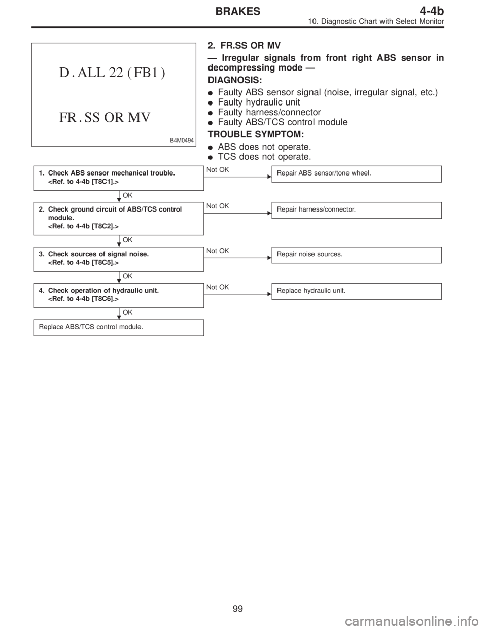
B4M0494
2. FR.SS OR MV
—Irregular signals from front right ABS sensor in
decompressing mode—
DIAGNOSIS:
�Faulty ABS sensor signal (noise, irregular signal, etc.)
�Faulty hydraulic unit
�Faulty harness/connector
�Faulty ABS/TCS control module
TROUBLE SYMPTOM:
�ABS does not operate.
�TCS does not operate.
1. Check ABS sensor mechanical trouble.
OK
�Not OK
Repair ABS sensor/tone wheel.
2. Check ground circuit of ABS/TCS control
module.
OK
�Not OK
Repair harness/connector.
3. Check sources of signal noise.
OK
�Not OK
Repair noise sources.
4. Check operation of hydraulic unit.
OK
�Not OK
Replace hydraulic unit.
Replace ABS/TCS control module.
�
�
�
�
99
4-4bBRAKES
10. Diagnostic Chart with Select Monitor
Page 1783 of 2248

�Faulty harness/connector
�Faulty AB")
B4M0498
G: TROUBLE CODE 24
1. FL.SS W.SPEED
—Irregular signals from front left ABS sensor—
DIAGNOSIS:
�Faulty ABS sensor signal (noise, irregular signal, etc.)
�Faulty harness/connector
�Faulty ABS/TCS control module
TROUBLE SYMPTOM:
�ABS and TCS do not operate.
NOTE:
The procedures used are the same as those for FR.SS
W.SPEED.
B4M0499
2. FL.SS OR MV
—Irregular signals from front left ABS sensor in
decompressing mode—
DIAGNOSIS:
�Faulty ABS sensor signal (noise, irregular signal, etc.)
�Faulty hydraulic unit
�Faulty harness/connector
�Faulty ABS/TCS control module
TROUBLE SYMPTOM:
�ABS and TCS do not operate.
NOTE:
The procedures used are the same as those for FR.SS OR
MV.
B4M0500
3. FL.SS OVER
—Excessive speed of front left ABS sensor signal—
DIAGNOSIS:
�Faulty ABS sensor signal (noise, irregular signal, etc.)
�Faulty harness/connector
�Faulty ABS/TCS control module
TROUBLE SYMPTOM:
�ABS and TCS do not operate.
NOTE:
The procedures used are the same as those for FR.SS
OVER.
102
4-4bBRAKES
10. Diagnostic Chart with Select Monitor
Page 1785 of 2248

�Faulty harness/connector
�Faulty AB")
B4M0503
I: TROUBLE CODE 26
1. RR.SS W.SPEED
—Irregular signals from rear right ABS sensor—
DIAGNOSIS:
�Faulty ABS sensor signal (noise, irregular signal, etc.)
�Faulty harness/connector
�Faulty ABS/TCS control module
TROUBLE SYMPTOM:
�ABS and TCS do not operate.
NOTE:
The procedures used are the same as those for FR.SS
W.SPEED.
B4M0504
2. RR.SS OR MV
—Irregular signals from rear right ABS sensor in
decompressing mode—
DIAGNOSIS:
�Faulty ABS sensor signal (noise, irregular signal, etc.)
�Faulty hydraulic unit
�Faulty harness/connector
�Faulty ABS/TCS control module
TROUBLE SYMPTOM:
�ABS and TCS do not operate.
NOTE:
The procedures used are the same as those for FR.SS OR
MV.
B4M0505
3. RR.SS OVER
—Excessive speed of rear right ABS sensor signal—
DIAGNOSIS:
�Faulty ABS sensor signal (noise, irregular signal, etc.)
�Faulty harness/connector
�Faulty ABS/TCS control module
TROUBLE SYMPTOM:
�ABS and TCS do not operate.
NOTE:
The procedures used are the same as those for FR.SS
OVER.
104
4-4bBRAKES
10. Diagnostic Chart with Select Monitor
Page 1787 of 2248

�Faulty harness/connector
�Faulty ABS")
B4M0508
K: TROUBLE CODE 28
1. RL.SS W.SPEED
—Irregular signals from rear left ABS sensor—
DIAGNOSIS:
�Faulty ABS sensor signal (noise, irregular signal, etc.)
�Faulty harness/connector
�Faulty ABS/TCS control module
TROUBLE SYMPTOM:
�ABS and TCS do not operate.
NOTE:
The procedures used are the same as those for FR.SS
W.SPEED.
B4M0509
2. RL.SS OR MV
—Irregular signals from rear left ABS sensor in
decompressing mode—
DIAGNOSIS:
�Faulty ABS sensor signal (noise, irregular signal, etc.)
�Faulty hydraulic unit
�Faulty harness/connector
�Faulty ABS/TCS control module
TROUBLE SYMPTOM:
�ABS and TCS do not operate.
NOTE:
The procedures used are the same as those for FR.SS OR
MV.
B4M0510
3. RL.SS OVER
—Excessive speed of rear left ABS sensor signal—
DIAGNOSIS:
�Faulty ABS sensor signal (noise, irregular signal, etc.)
�Faulty harness/connector
�Faulty ABS/TCS control module
TROUBLE SYMPTOM:
�ABS and TCS do not operate.
NOTE:
The procedures used are the same as those for FR.SS
OVER.
106
4-4bBRAKES
10. Diagnostic Chart with Select Monitor
Page 1788 of 2248
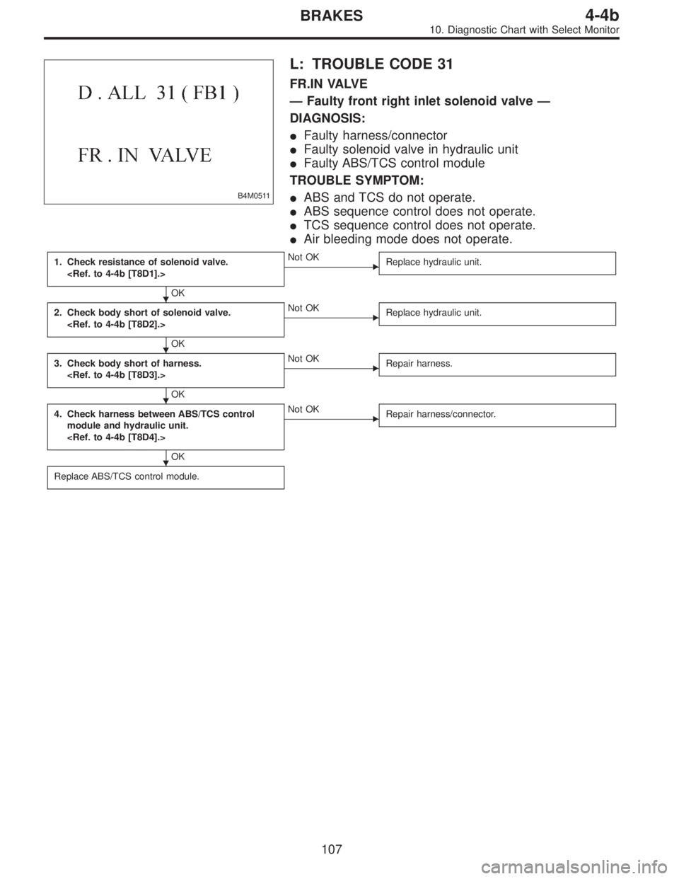
B4M0511
L: TROUBLE CODE 31
FR.IN VALVE
—Faulty front right inlet solenoid valve—
DIAGNOSIS:
�Faulty harness/connector
�Faulty solenoid valve in hydraulic unit
�Faulty ABS/TCS control module
TROUBLE SYMPTOM:
�ABS and TCS do not operate.
�ABS sequence control does not operate.
�TCS sequence control does not operate.
�Air bleeding mode does not operate.
1. Check resistance of solenoid valve.
OK
�Not OK
Replace hydraulic unit.
2. Check body short of solenoid valve.
OK
�Not OK
Replace hydraulic unit.
3. Check body short of harness.
OK
�Not OK
Repair harness.
4. Check harness between ABS/TCS control
module and hydraulic unit.
OK
�Not OK
Repair harness/connector.
Replace ABS/TCS control module.
�
�
�
�
107
4-4bBRAKES
10. Diagnostic Chart with Select Monitor