Page 1664 of 2248
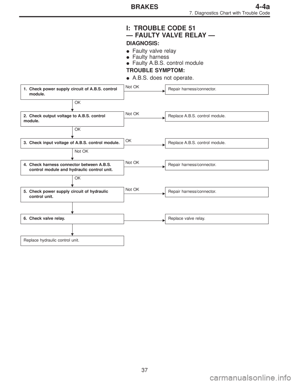
I: TROUBLE CODE 51
—FAULTY VALVE RELAY—
DIAGNOSIS:
�Faulty valve relay
�Faulty harness
�Faulty A.B.S. control module
TROUBLE SYMPTOM:
�A.B.S. does not operate.
1. Check power supply circuit of A.B.S. control
module.
OK
�Not OK
Repair harness/connector.
2. Check output voltage to A.B.S. control
module.
OK
�Not OK
Replace A.B.S. control module.
3. Check input voltage of A.B.S. control module.
Not OK
�OK
Replace A.B.S. control module.
4. Check harness connector between A.B.S.
control module and hydraulic control unit.
OK
�Not OK
Repair harness/connector.
5. Check power supply circuit of hydraulic
control unit.�Not OK
Repair harness/connector.
6. Check valve relay.�Replace valve relay.
Replace hydraulic control unit.
�
�
�
�
�
�
37
4-4aBRAKES
7. Diagnostics Chart with Trouble Code
Page 1666 of 2248
 Turn ignition switch OFF.
2) Disconnect connector from A.B.S. control module.
3) Disconnect connector cover from connector. <Ref. to
4-4a")
B4M0267B
2. CHECK OUTPUT VOLTAGE TO A.B.S. CONTROL
MODULE.
1) Turn ignition switch OFF.
2) Disconnect connector from A.B.S. control module.
3) Disconnect connector cover from connector.
4-4a [T7C2].>
4) Connect connector to A.B.S. control module.
5) Turn ignition switch ON.
6) Measure voltage between A.B.S. control module con-
nector terminals.
Connector & terminal / Specified voltage:
(P3) No. 17—No. 20 / 10—12 V
B4M0268B
3. CHECK INPUT VOLTAGE OF A.B.S. CONTROL
MODULE.
1) Turn ignition switch ON.
2) Measure voltage between A.B.S. control module con-
nector terminals.
Connector & terminal / Specified voltage:
(P3) No. 32—No. 20 / 10—12 V
B4M0269B
4. CHECK HARNESS CONNECTOR BETWEEN A.B.S.
CONTROL MODULE AND HYDRAULIC CONTROL
UNIT.
1) Turn ignition switch OFF.
2) Disconnect connector from A.B.S. control module and
hydraulic control unit.
3) Measure resistance between A.B.S. control module and
hydraulic control unit.
Connector & terminal / Specified resistance:
(P3) No. 17—(F9) No.6/0Ω
(P3) No. 32—(F9) No. 11 / 0Ω
(P3) No. 27—(F9) No. 12 / 0Ω
39
4-4aBRAKES
7. Diagnostics Chart with Trouble Code
Page 1667 of 2248
B4M0262B
5. CHECK POWER SUPPLY CIRCUIT OF HYDRAULIC
CONTROL UNIT.
1) Turn ignition switch OFF.
2) Disconnect connector from hydraulic control unit.
3) Turn ignition switch ON.
4) Measure voltage between hydraulic control unit and
body.
Connector & terminal / Specified voltage:
(F8) No. 1—Body / 10—12 V
G4M0690
6. CHECK VALVE RELAY.
1) Remove valve relay.
2) Attach circuit tester probes to terminals, as shown in
figure.
3) Measure resistance between respective terminals.
Terminal / Specified resistance:
No. 87—No. 30 / 0Ω(when 12 volts applied.)
No. 87—No.30/1MΩ(when no volts applied.)
No. 87a—No.30/1MΩ(when 12 volts applied.)
No. 87a—No. 30 / 0Ω(when no volts applied.)
40
4-4aBRAKES
7. Diagnostics Chart with Trouble Code
Page 1668 of 2248
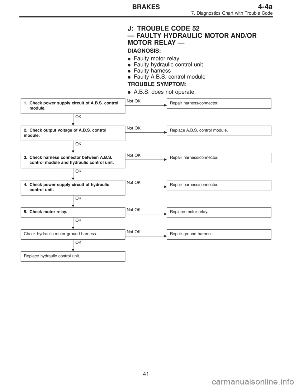
J: TROUBLE CODE 52
—FAULTY HYDRAULIC MOTOR AND/OR
MOTOR RELAY—
DIAGNOSIS:
�Faulty motor relay
�Faulty hydraulic control unit
�Faulty harness
�Faulty A.B.S. control module
TROUBLE SYMPTOM:
�A.B.S. does not operate.
1. Check power supply circuit of A.B.S. control
module.
OK
�Not OK
Repair harness/connector.
2. Check output voltage of A.B.S. control
module.
OK
�Not OK
Replace A.B.S. control module.
3. Check harness connector between A.B.S.
control module and hydraulic control unit.
OK
�Not OK
Repair harness/connector.
4. Check power supply circuit of hydraulic
control unit.
OK
�Not OK
Repair harness/connector.
5. Check motor relay.
OK
�Not OK
Replace motor relay.
Check hydraulic motor ground harness.
OK
�Not OK
Repair ground harness.
Replace hydraulic control unit.
�
�
�
�
�
�
41
4-4aBRAKES
7. Diagnostics Chart with Trouble Code
Page 1670 of 2248
 Turn ignition switch OFF.
2) Disconnect connector from A.B.S. control module.
3) Disconnect connector cover from connector. <Ref. to
4-4a")
B4M0267B
2. CHECK OUTPUT VOLTAGE OF A.B.S. CONTROL
MODULE.
1) Turn ignition switch OFF.
2) Disconnect connector from A.B.S. control module.
3) Disconnect connector cover from connector.
4-4a [T7C2].>
4) Connect connector to A.B.S. control module.
5) Turn ignition switch ON.
6) Measure voltage between A.B.S. control module con-
nector terminals.
Connector & terminal / Specified voltage:
(P3) No. 17—No. 20 / 10—12 V
B4M0275B
3. CHECK HARNESS CONNECTOR BETWEEN A.B.S.
CONTROL MODULE AND HYDRAULIC CONTROL
UNIT.
1) Turn ignition switch OFF.
2) Disconnect connector from A.B.S. control module.
3) Disconnect connector from hydraulic control unit.
4) Measure resistance between A.B.S. control module
connector and hydraulic control unit connector.
Connector & terminal / Specified resistance:
(P3) No. 17—(F9) No.6/0Ω
(P3) No. 28—(F9) No.5/0Ω
(P3) No. 14—(F9) No.7/0Ω
B4M0276B
4. CHECK POWER SUPPLY CIRCUIT OF HYDRAULIC
CONTROL UNIT.
1) Turn ignition switch OFF.
2) Disconnect connector from hydraulic control unit.
3) Measure voltage between hydraulic control unit connec-
tor and body.
Connector & terminal / Specified voltage:
(F8) No. 2—Body / 10—12 V
43
4-4aBRAKES
7. Diagnostics Chart with Trouble Code
Page 1679 of 2248
 roads�Stopping distance may sometimes be longer
than for models not equipped with A.B.S.
Check if stopping
d")
B: EXCESSIVE STOPPING DISTANCE
Stopping distance is
too great.�Snowy or sandy (low“µ”) roads�Stopping distance may sometimes be longer
than for models not equipped with A.B.S.
Check if stopping
distance continues
to be excessive
when A.B.S. is inac-
tivated by discon-
necting hydraulic
control unit connec-
tor.
�Ye s�Check wheels and
associated parts for
looseness.
Check tires for
improper specifica-
tions.
Check G sensor for
improper operation.
Bleed air from brake
line.
Check brake system
for abnormalities.
�No�Hydraulic control
unit operation
check.
[W15B0].>�No�Check hydraulic
control unit.
�Ye s�Go to A-�1.
C: IMPROPER PEDAL OPERATION
Pedal does not
operate prop-
erly.
�Long pedal
stroke�
Check if brakes
operate prop-
erly.
�Ye s�On A.B.S. equipped model, pedal stroke may be
slightly longer than for models which are not
equipped with A.B.S.
�No�Bleed air from
brake line.
�Short pedal
stroke�
Check if brakes
operate prop-
erly.
�Ye s�Normal
�No�Check if brakes
operate prop-
erly when
A.B.S. is inacti-
vated by dis-
connecting
hydraulic con-
trol unit connec-
tor.�Ye s�Go to A-�1.
�No�Check brake
system.
�
52
4-4aBRAKES
8. General Diagnostics Chart
Page 1682 of 2248

1. Supplemental Restraint System
“Airbag”
Airbag system wiring harness is routed near the ABS/TCS
control module, ABS sensor and hydraulic control unit.
CAUTION:
�All Airbag system wiring harness and connectors
are colored yellow. Do not use electrical test equip-
ment on these circuit.
�Be careful not to damage Airbag system wiring har-
ness when servicing the ABS/TCS control module,
ABS sensor and hydraulic control unit.
2. Pre-inspection
Before performing diagnostics, check the following items
which might affect ABS/TCS problems:
A: MECHANICAL INSPECTION
1. POWER SUPPLY
1) Measure battery voltage and specific gravity of electro-
lyte.
Standard voltage: 12 V, or more
Specific gravity: Above 1.260
2) Check the condition of the main and other fuses, and
harnesses and connectors. Also check for proper ground-
ing.
2. BRAKE FLUID
1) Check brake fluid level.
2) Check brake fluid leakage.
3. BRAKE DRAG
Check brake drag.
4. BRAKE PAD AND ROTOR
Check brake pad and rotor.
5. TIRE SPECIFICATIONS, TIRE WEAR AND AIR
PRESSURE
Check tire specifications, tire wear and air pressure.
to 4-2 [S1A0].>
2
4-4bBRAKES
1. Supplemental Restraint System“Airbag”- 2. Pre-inspection
Page 1683 of 2248

1. Supplemental Restraint System
“Airbag”
Airbag system wiring harness is routed near the ABS/TCS
control module, ABS sensor and hydraulic control unit.
CAUTION:
�All Airbag system wiring harness and connectors
are colored yellow. Do not use electrical test equip-
ment on these circuit.
�Be careful not to damage Airbag system wiring har-
ness when servicing the ABS/TCS control module,
ABS sensor and hydraulic control unit.
2. Pre-inspection
Before performing diagnostics, check the following items
which might affect ABS/TCS problems:
A: MECHANICAL INSPECTION
1. POWER SUPPLY
1) Measure battery voltage and specific gravity of electro-
lyte.
Standard voltage: 12 V, or more
Specific gravity: Above 1.260
2) Check the condition of the main and other fuses, and
harnesses and connectors. Also check for proper ground-
ing.
2. BRAKE FLUID
1) Check brake fluid level.
2) Check brake fluid leakage.
3. BRAKE DRAG
Check brake drag.
4. BRAKE PAD AND ROTOR
Check brake pad and rotor.
5. TIRE SPECIFICATIONS, TIRE WEAR AND AIR
PRESSURE
Check tire specifications, tire wear and air pressure.
to 4-2 [S1A0].>
2
4-4bBRAKES
1. Supplemental Restraint System“Airbag”- 2. Pre-inspection
 Turn ignition switch OFF.
2) Disconnect connector from hydraulic control unit.
3) Turn ignition switch ON.
4) Measure voltage betwe")