Page 819 of 2248
B4M0628
G: INSTALLATION
1) Install hydraulic unit and bracket.
Tightening torque:
32±7 N⋅m (3.3±0.7 kg-m, 23.9±5.1 ft-lb)
2) Connect brake pipes to their correct hydraulic unit con-
nections.
3) Connect connector to hydraulic unit.
4) Install canister.
5) Install air cleaner case.
6) Install air intake duct.
7) Connect ground cable to battery.
CAUTION:
Cover relay securely with rubber boot.
21. ABS/TCS Control Module
A: REMOVAL
1) Disconnect ground cable from battery.
2) Remove floor mat located under lower right side of front
seat.
B4M0643A
3) Remove screw which secure ABS/TCS control module
from the body.
4) Disconnect connector from ABS/TCS control module.
B: INSPECTION
Check that connector is connected correctly and that con-
nector terminal sliding resistance is correct.
99
4-4SERVICE PROCEDURE
20. Hydraulic Unit for ABS/TCS System - 21. ABS/TCS Control Module
Page 849 of 2248
4. Control Unit
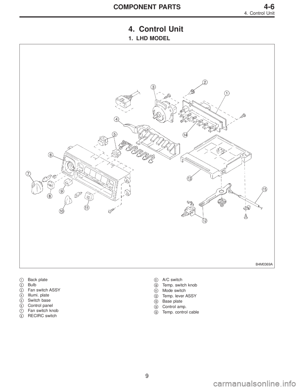
1. LHD MODEL
B4M0369A
�1Back plate
�
2Bulb
�
3Fan switch ASSY
�
4Illumi. plate
�
5Switch base
�
6Control panel
�
7Fan switch knob
�
8RECIRC switch�
9A/C switch
�
10Temp. switch knob
�
11Mode switch
�
12Temp. lever ASSY
�
13Base plate
�
14Control amp.
�
15Temp. control cable
9
4-6COMPONENT PARTS
4. Control Unit
Page 850 of 2248
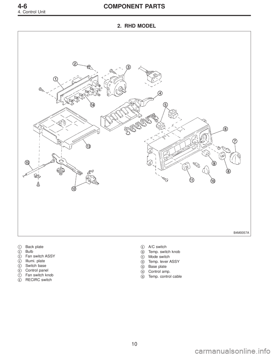
2. RHD MODEL
B4M0057A
�1Back plate
�
2Bulb
�
3Fan switch ASSY
�
4Illumi. plate
�
5Switch base
�
6Control panel
�
7Fan switch knob
�
8RECIRC switch�
9A/C switch
�
10Temp. switch knob
�
11Mode switch
�
12Temp. lever ASSY
�
13Base plate
�
14Control amp.
�
15Temp. control cable
10
4-6COMPONENT PARTS
4. Control Unit
Page 851 of 2248
1. Supplemental Restraint System
“Airbag”
Airbag system wiring harness is routed near the instrument
panel, heater unit, blower motor and control unit.
CAUTION:
�All Airbag system wiring harness and connectors
are colored yellow. Do not use electrical test equip-
ment on these circuit.
�Be careful not to damage Airbag system wiring har-
ness when servicing the instrument panel, heater unit,
blower motor and control unit.
2. Heater Unit
A: REMOVAL AND INSTALLATION
1) Disconnect GND cable from battery.
2) Remove heater hoses (inlet, outlet) in engine compart-
ment.
NOTE:
Drain as much coolant from heater unit as possible, and
plug disconnected hose with cloth.
3) Remove instrument panel.
4) Remove steering support beam.
5) Remove evaporator. (With A/C model)
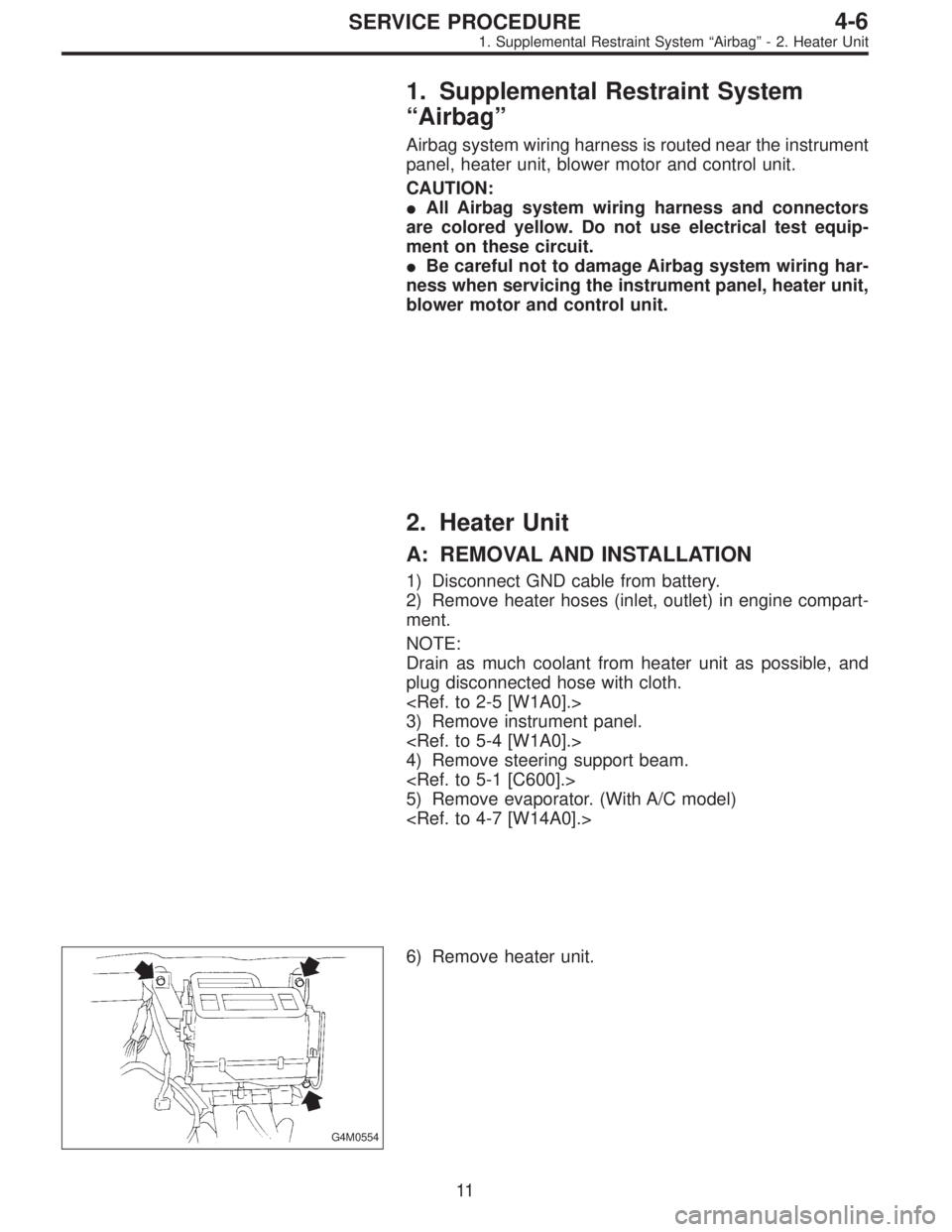
G4M0554
6) Remove heater unit.
11
4-6SERVICE PROCEDURE
1. Supplemental Restraint System“Airbag”- 2. Heater Unit
Page 852 of 2248
1. Supplemental Restraint System
“Airbag”
Airbag system wiring harness is routed near the instrument
panel, heater unit, blower motor and control unit.
CAUTION:
�All Airbag system wiring harness and connectors
are colored yellow. Do not use electrical test equip-
ment on these circuit.
�Be careful not to damage Airbag system wiring har-
ness when servicing the instrument panel, heater unit,
blower motor and control unit.
2. Heater Unit
A: REMOVAL AND INSTALLATION
1) Disconnect GND cable from battery.
2) Remove heater hoses (inlet, outlet) in engine compart-
ment.
NOTE:
Drain as much coolant from heater unit as possible, and
plug disconnected hose with cloth.
3) Remove instrument panel.
4) Remove steering support beam.
5) Remove evaporator. (With A/C model)
G4M0554
6) Remove heater unit.
11
4-6SERVICE PROCEDURE
1. Supplemental Restraint System“Airbag”- 2. Heater Unit
Page 855 of 2248
B5M0027
4. Control Unit
A: REMOVAL
1) Disconnect GND cable from battery.
2) Set temperature control lever to“FULL COLD”position.
3) Remove temperature control cable from heater unit.
NOTE:
Do not attempt to move link of heater unit during installa-
tion.
B4M0370
4) Remove cup holder.
5) Remove center panel and then disconnect connector.
B4M0059
6) Remove control unit assembly and disconnect connec-
tor.
B4M0060A
B: INSPECTION
1. FAN SWITCH
Check continuity between terminals at each switch posi-
tion.
LHD model
Switch
positionTerminals
123456
1��
�
2���
3���
4���
GND IGN
13
4-6SERVICE PROCEDURE
4. Control Unit
Page 856 of 2248
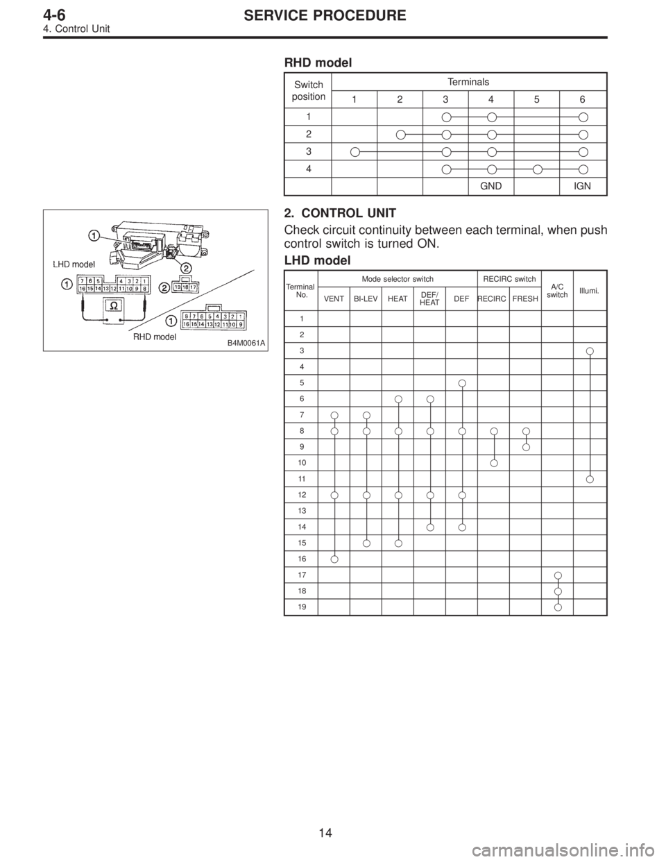
RHD model
Switch
positionTerminals
123456
1�
��
2�
���
3�
���
4�
���
GND IGN
B4M0061A
2. CONTROL UNIT
Check circuit continuity between each terminal, when push
control switch is turned ON.
LHD model
Terminal
No.Mode selector switch RECIRC switch
A/C
switchIllumi.
VENT BI-LEV HEATDEF/
HEATDEF RECIRC FRESH
1
2
3�
4
5�
6��
7��
8�������
9�
10�
11�
12�
����
13
14��
15��
16�
17�
18�
19�
14
4-6SERVICE PROCEDURE
4. Control Unit
Page 857 of 2248
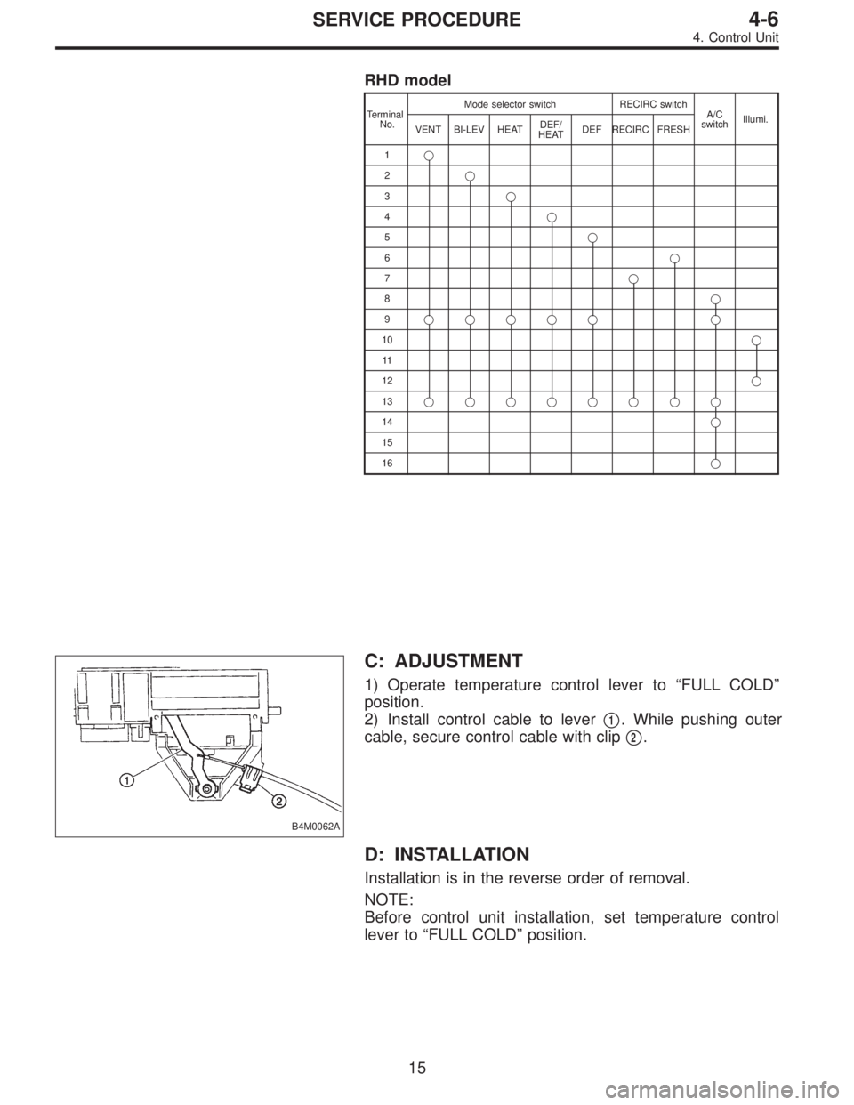
RHD model
Terminal
No.Mode selector switch RECIRC switch
A/C
switchIllumi.
VENT BI-LEV HEATDEF/
HEATDEF RECIRC FRESH
1�
2�
3�
4�
5�
6�
7�
8�
9������
10�
11
12�
13��������
14�
15
16�
B4M0062A
C: ADJUSTMENT
1) Operate temperature control lever to“FULL COLD”
position.
2) Install control cable to lever�
1. While pushing outer
cable, secure control cable with clip�
2.
D: INSTALLATION
Installation is in the reverse order of removal.
NOTE:
Before control unit installation, set temperature control
lever to“FULL COLD”position.
15
4-6SERVICE PROCEDURE
4. Control Unit
 Install hydraulic unit and bracket.
Tightening torque:
32±7 N⋅m (3.3±0.7 kg-m, 23.9±5.1 ft-lb)
2) Connect brake pipes to their correct hydraulic unit con-
nections. <Re")

 Disconnect GND cable from battery.
2) Set temperature control lever to“FULL COLD”position.
3) Remove temperature control cable from heater unit.
NOTE:
Do not")