Page 644 of 2248
4. Steering Gearbox (Power Steering
System) [RHD model]
NOTE:
For disassembly and assembly of gearbox unit, refer to
section Control Valve (Power Steering Gearbox).
B4M0666A
Tightening torque: N⋅m (kg-m, ft-lb)
T1: 20±4 (2.0±0.4, 14.5±2.9)
T2: 25±5 (2.5±0.5, 18.1±3.6)
T3: 39±10 (4.0±1.0, 29±7)
T4: 64±10 (6.5±1.0, 47±7)
T5: 78±10 (8.0±1.0, 58±7)
T6: 83±5 (8.5±0.5, 61.5±3.6)
28
4-3SERVICE PROCEDURE
4. Steering Gearbox (Power Steering System) [RHD model]
Page 657 of 2248

2. OIL LEAK CHECK PROCEDURE AND
REPLACEMENT PARTS
NOTE:
Parts requiring replacement are described in the smallest
unit of spare parts including damaged parts and spare
parts damaged. In actual disassembly work, accidental
damage as well as inevitable damage to some related
parts must be taken into account, and spare parts for them
must also be prepared. However, it is essential to pinpoint
the cause of trouble, and limit the number of replacement
parts as much as possible.
1) Leakage from“a”
The oil seal is damaged. Replace valve assembly with a
new one.
2) Leakage from“b”
The torsion bar O-ring is damaged. Replace valve assem-
bly with a new one.
3) Leakage from“c”
The oil seal is damaged. Replace valve assembly with a
new one.
4) Leakage from“d”
The pipe is damaged. Replace the faulty pipe or O-ring.
5) If leak is other than a, b, c, or d, and if oil is leaking from
the gearbox, move the right and left boots toward tie-rod
end side, respectively, with the gearbox mounted to the
vehicle, and remove oil from the surrounding portions.
Then, turn the steering wheel from lock to lock 30 to 40
times with the engine running, then make comparison of
the leaked portion immediately after and several hours
after this operation.
6) Leakage from“e”
The cylinder seal is damaged. Replace rack bush with a
new one.
7) Leakage from“f”
There are two possible causes. Take following step first.
Remove the pipe assembly B from the valve housing, and
close the circuit with ST.
ST 926420000 PLUG
Turn the steering wheel from lock to lock 30 to 40 times
with the engine running, then make comparison of the
leaked portion between immediately after and several
hours after this operation.
CAUTION:
�If leakage from“f”is noted again:
The oil seal of pinion and valve assembly is damaged.
Replace pinion and valve assembly with a new one. Or
replace the oil seal and the parts that are damaged
during disassembly with new ones.
�If oil stops leaking from“f”:
The oil seal of rack housing is damaged.
Replace the oil seal and the parts that are damaged
during disassembly with new ones.
41
4-3SERVICE PROCEDURE
5. Control Valve (Power Steering Gearbox) [LHD model]
Page 666 of 2248

2. OIL LEAK CHECK PROCEDURE AND
REPLACEMENT PARTS
NOTE:
Parts requiring replacement are described in the smallest
unit of spare parts including damaged parts and spare
parts damaged. In actual disassembly work, accidental
damage as well as inevitable damage to some related
parts must be taken into account, and spare parts for them
must also be prepared. However, it is essential to pinpoint
the cause of trouble, and limit the number of replacement
parts as much as possible.
1) Leakage from“a”
The oil seal is damaged. Replace valve assembly with a
new one.
2) Leakage from“b”
The torsion bar O-ring is damaged. Replace valve assem-
bly with a new one.
3) Leakage from“c”
The oil seal is damaged. Replace valve assembly with a
new one.
4) Leakage from“d”
The pipe is damaged. Replace the faulty pipe or O-ring.
5) If leak is other than a, b, c, or d, and if oil is leaking from
the gearbox, move the right and left boots toward tie-rod
end side, respectively, with the gearbox mounted to the
vehicle, and remove oil from the surrounding portions.
Then, turn the steering wheel from lock to lock 30 to 40
times with the engine running, then make comparison of
the leaked portion immediately after and several hours
after this operation.
6) Leakage from“e”
There are two possible causes. Take following step first.
Remove the pipe assembly B from the valve housing, and
close the circuit with ST.
ST 926420000 PLUG
Turn the steering wheel from lock to lock 30 to 40 times
with the engine running, then make comparison of the
leaked portion between immediately after and several
hours after this operation.
CAUTION:
�If leakage from“e”is noted again:
The oil seal of pinion and valve assembly is damaged.
Replace pinion and valve assembly with a new one. Or
replace the oil seal and the parts that are damaged
during disassembly with new ones.
�If oil stops leaking from“e”:
The oil seal of rack housing is damaged.
Replace the oil seal and the parts that are damaged
during disassembly with new ones.
50
4-3SERVICE PROCEDURE
6. Control Valve (Power Steering Gearbox) [RHD model]
Page 667 of 2248
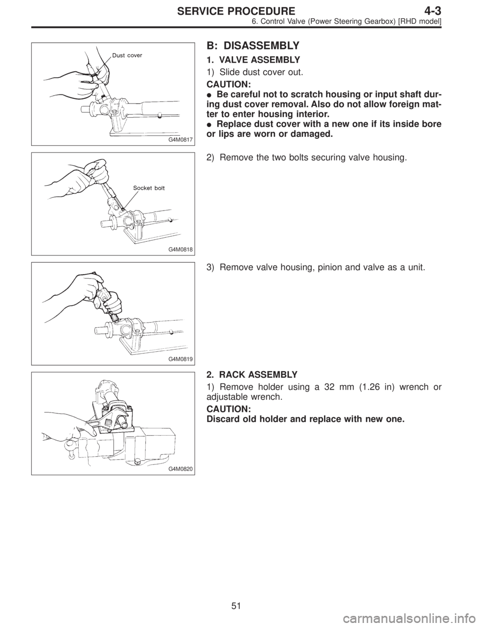
G4M0817
B: DISASSEMBLY
1. VALVE ASSEMBLY
1) Slide dust cover out.
CAUTION:
�Be careful not to scratch housing or input shaft dur-
ing dust cover removal. Also do not allow foreign mat-
ter to enter housing interior.
�Replace dust cover with a new one if its inside bore
or lips are worn or damaged.
G4M0818
2) Remove the two bolts securing valve housing.
G4M0819
3) Remove valve housing, pinion and valve as a unit.
G4M0820
2. RACK ASSEMBLY
1) Remove holder using a 32 mm (1.26 in) wrench or
adjustable wrench.
CAUTION:
Discard old holder and replace with new one.
51
4-3SERVICE PROCEDURE
6. Control Valve (Power Steering Gearbox) [RHD model]
Page 668 of 2248
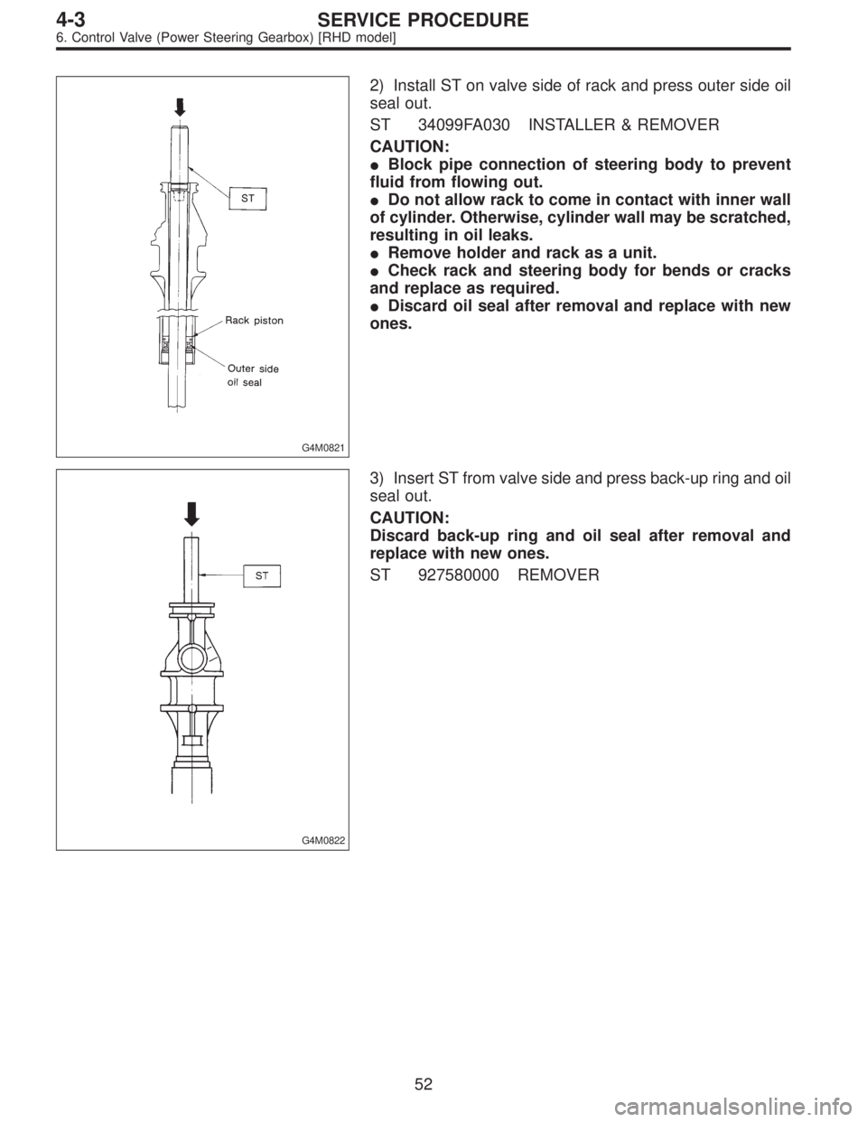
G4M0821
2) Install ST on valve side of rack and press outer side oil
seal out.
ST 34099FA030 INSTALLER & REMOVER
CAUTION:
�Block pipe connection of steering body to prevent
fluid from flowing out.
�Do not allow rack to come in contact with inner wall
of cylinder. Otherwise, cylinder wall may be scratched,
resulting in oil leaks.
�Remove holder and rack as a unit.
�Check rack and steering body for bends or cracks
and replace as required.
�Discard oil seal after removal and replace with new
ones.
G4M0822
3) Insert ST from valve side and press back-up ring and oil
seal out.
CAUTION:
Discard back-up ring and oil seal after removal and
replace with new ones.
ST 927580000 REMOVER
52
4-3SERVICE PROCEDURE
6. Control Valve (Power Steering Gearbox) [RHD model]
Page 729 of 2248
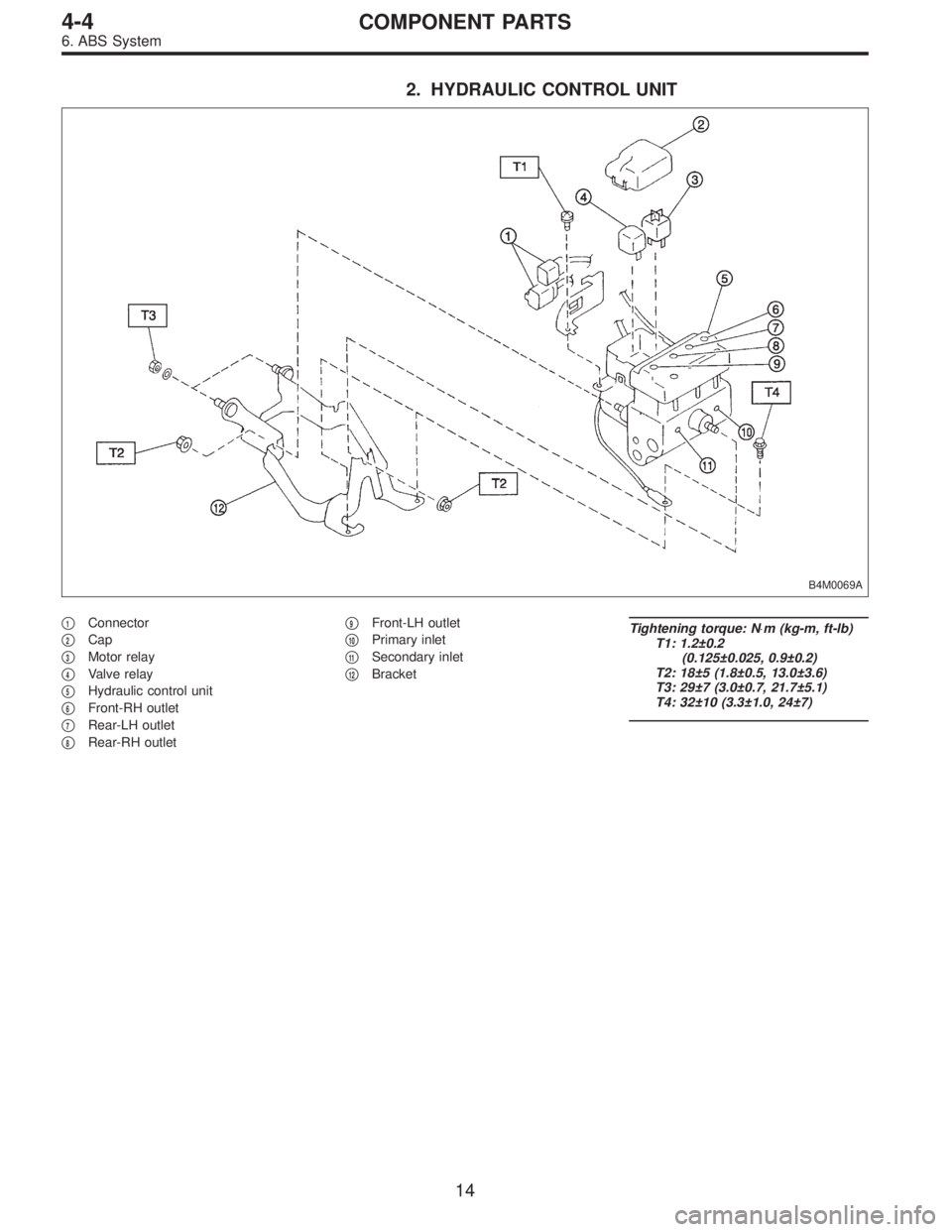
2. HYDRAULIC CONTROL UNIT
B4M0069A
�1Connector
�
2Cap
�
3Motor relay
�
4Valve relay
�
5Hydraulic control unit
�
6Front-RH outlet
�
7Rear-LH outlet
�
8Rear-RH outlet�
9Front-LH outlet
�
10Primary inlet
�
11Secondary inlet
�
12Bracket
Tightening torque: N⋅m (kg-m, ft-lb)
T1: 1.2±0.2
(0.125±0.025, 0.9±0.2)
T2: 18±5 (1.8±0.5, 13.0±3.6)
T3: 29±7 (3.0±0.7, 21.7±5.1)
T4: 32±10 (3.3±1.0, 24±7)
14
4-4COMPONENT PARTS
6. ABS System
Page 733 of 2248
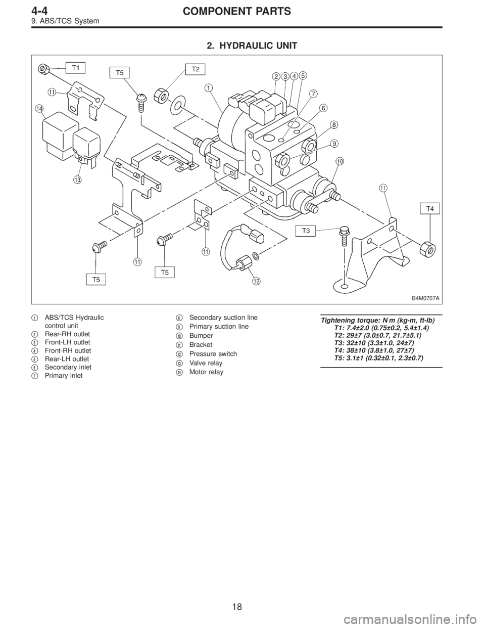
2. HYDRAULIC UNIT
B4M0707A
�1ABS/TCS Hydraulic
control unit
�
2Rear-RH outlet
�
3Front-LH outlet
�
4Front-RH outlet
�
5Rear-LH outlet
�
6Secondary inlet
�
7Primary inlet�
8Secondary suction line
�
9Primary suction line
�
10Bumper
�
11Bracket
�
12Pressure switch
�
13Valve relay
�
14Motor relay
Tightening torque: N⋅m (kg-m, ft-lb)
T1: 7.4±2.0 (0.75±0.2, 5.4±1.4)
T2: 29±7 (3.0±0.7, 21.7±5.1)
T3: 32±10 (3.3±1.0, 24±7)
T4: 38±10 (3.8±1.0, 27±7)
T5: 3.1±1 (0.32±0.1, 2.3±0.7)
18
4-4COMPONENT PARTS
9. ABS/TCS System
Page 773 of 2248

5) Perform these steps for the brakes connecting to the
secondary chamber of master cylinder, first, and then for
the ones con")
Air bleeder tightening torque:
8±1 N⋅m (0.8±0.1 kg-m, 5.8±0.7 ft-lb)
5) Perform these steps for the brakes connecting to the
secondary chamber of master cylinder, first, and then for
the ones connecting to primary chamber. With all proce-
dures completed, fully depress the brake pedal and keep
it in that position for approximately 20 seconds to make
sure that there is no leak evident in the entire system.
G4M0436
6) Perform sequence control. (With ABS model)
[W15C1].>
7) Check the pedal stroke.
While the engine is idling, depress the brake pedal with a
490 N (50 kg, 110 lb) load and measure the distance
between the brake pedal and steering wheel. With the
brake pedal released, measure the distance between the
pedal and steering wheel again. The difference between
the two measurements must be more than specified.
Specified pedal stroke:
Without ABS
90 mm (3.54 in)
With ABS
95 mm (3.74 in)
When depressing brake pedal with a 490 N (50 kg,
110 lb) load.
(1) Models without ABS
If the distance is more than specifications, there is a
possibility that air is in the brake line. Bleed air from the
brake line.
(2) Models with ABS
If the distance is more than specifications, there is a
possibility air is in the inside of the hydraulic unit.
Therefore, air must be bled from the inside of the
hydraulic unit to the brake pipes in accordance with the
bleeding sequence control.
8) Add brake fluid to the required level (MAX. level) of
reserve tank.
9) As a final step, test run the vehicle at low speed and
apply brakes relatively hard 2 to 3 times to ensure that
brakes provide normal braking action on all four wheels
without dragging and uneven braking.
56
4-4SERVICE PROCEDURE
11. Air Bleeding (Without TCS model)
![SUBARU LEGACY 1995 Service Repair Manual 4. Steering Gearbox (Power Steering
System) [RHD model]
NOTE:
For disassembly and assembly of gearbox unit, refer to
section Control Valve (Power Steering Gearbox).
B4M0666A
Tightening torque: N⋅m (](/manual-img/17/57432/w960_57432-643.png "SUBARU LEGACY 1995 Service Repair Manual 4. Steering Gearbox (Power Steering
System) [RHD model]
NOTE:
For disassembly and assembly of gearbox unit, refer to
section Control Valve (Power Steering Gearbox).
B4M0666A
Tightening torque: N⋅m (")