Page 1638 of 2248
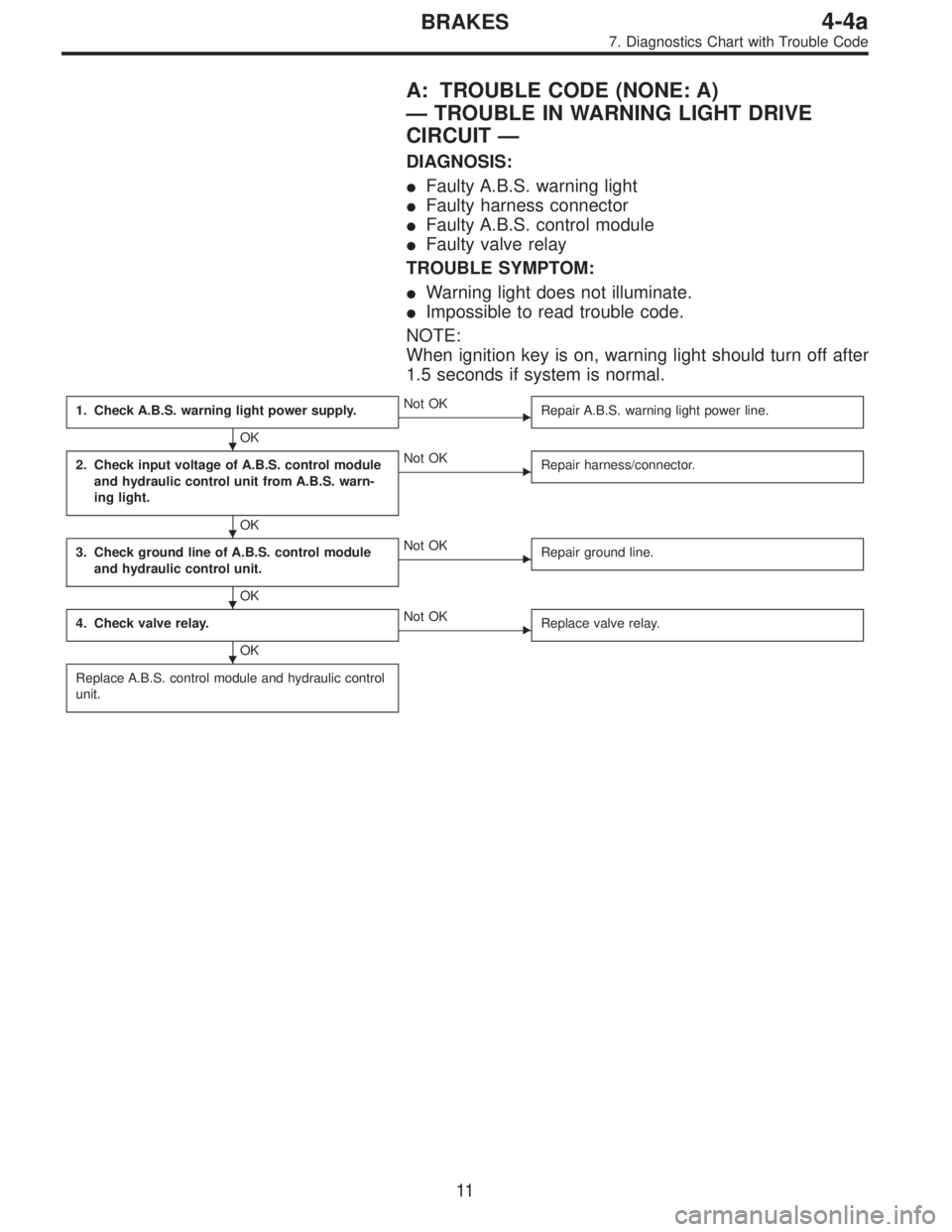
A: TROUBLE CODE (NONE: A)
—TROUBLE IN WARNING LIGHT DRIVE
CIRCUIT—
DIAGNOSIS:
�Faulty A.B.S. warning light
�Faulty harness connector
�Faulty A.B.S. control module
�Faulty valve relay
TROUBLE SYMPTOM:
�Warning light does not illuminate.
�Impossible to read trouble code.
NOTE:
When ignition key is on, warning light should turn off after
1.5 seconds if system is normal.
1. Check A.B.S. warning light power supply.
OK
�Not OK
Repair A.B.S. warning light power line.
2. Check input voltage of A.B.S. control module
and hydraulic control unit from A.B.S. warn-
ing light.
OK
�Not OK
Repair harness/connector.
3. Check ground line of A.B.S. control module
and hydraulic control unit.
OK
�Not OK
Repair ground line.
4. Check valve relay.
OK
�Not OK
Replace valve relay.
Replace A.B.S. control module and hydraulic control
unit.
�
�
�
�
11
4-4aBRAKES
7. Diagnostics Chart with Trouble Code
Page 1640 of 2248
 Turn ignition switch OFF and remove combination
meter.
2) Disconnect connector from A.")
B4M0236B
2. CHECK INPUT VOLTAGE OF A.B.S. CONTROL
MODULE AND HYDRAULIC CONTROL UNIT FROM
A.B.S. WARNING LIGHT.
1) Turn ignition switch OFF and remove combination
meter.
2) Disconnect connector from A.B.S. control module and
hydraulic control unit.
3) Turn ignition switch ON.
4) Measure voltage between A.B.S. control module and
body, and between hydraulic control unit and body.
Connector & terminal / Specified voltage:
(P3) No. 29—body / 10—12 V
(F9) No. 10—body / 10—12 V
B4M0237B
3. CHECK GROUND LINE OF A.B.S. CONTROL
MODULE AND HYDRAULIC CONTROL UNIT.
Measure resistance between A.B.S. control module and
body, and between hydraulic control unit and body.
Connector & terminal / Specified resistance:
(P3) No. 10—body / 0Ω
(P3) No. 20—body / 0Ω
(P3) No. 34—body / 0Ω
(F9) No. 8—body / 0Ω
G4M0690
4. CHECK VALVE RELAY.
1) Remove valve relay.
2) Attach circuit tester probes to terminals, as shown in
figure.
3) Measure resistance between respective terminals.
Terminal / Specified resistance:
No. 87—No. 30 / 0Ω(when 12 volts applied.)
No. 87—No.30/1MΩ(when no volts applied.)
No. 87a—No.30/1MΩ(when 12 volts applied.)
No. 87a—No. 30 / 0Ω(when no volts applied.)
13
4-4aBRAKES
7. Diagnostics Chart with Trouble Code
Page 1641 of 2248
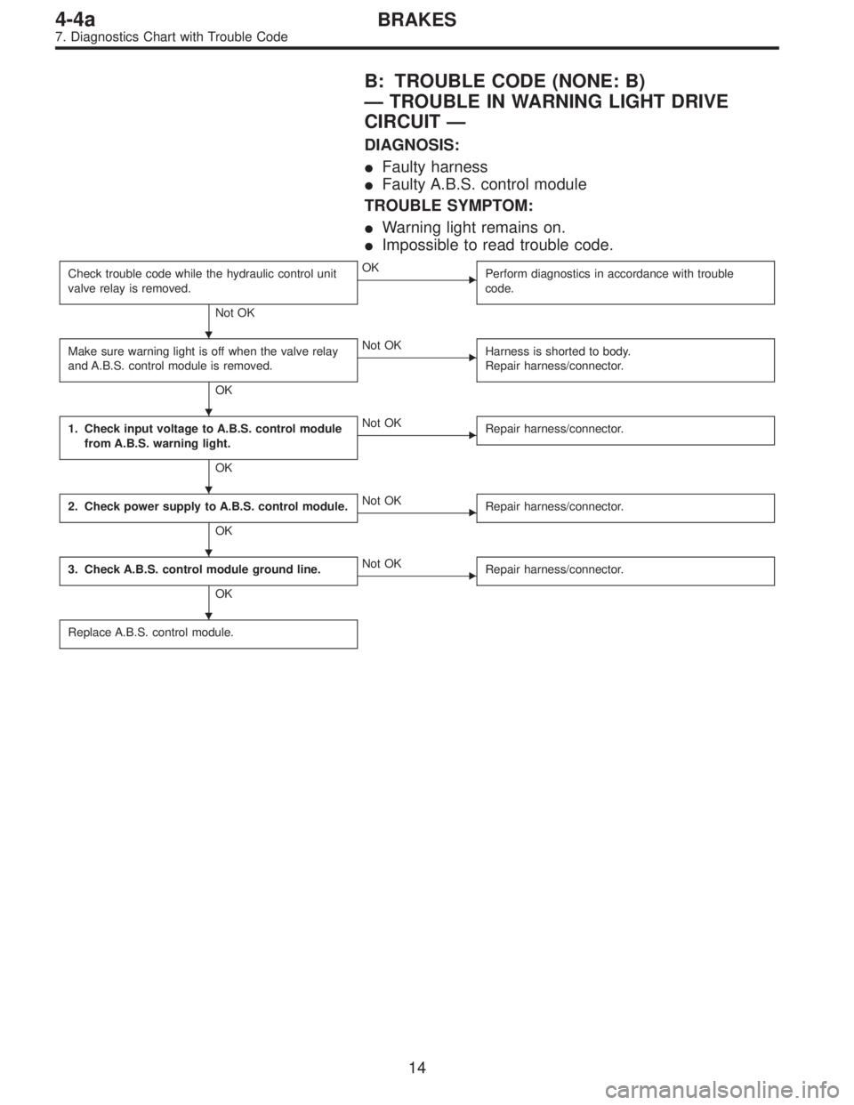
B: TROUBLE CODE (NONE: B)
—TROUBLE IN WARNING LIGHT DRIVE
CIRCUIT—
DIAGNOSIS:
�Faulty harness
�Faulty A.B.S. control module
TROUBLE SYMPTOM:
�Warning light remains on.
�Impossible to read trouble code.
Check trouble code while the hydraulic control unit
valve relay is removed.
Not OK
�OK
Perform diagnostics in accordance with trouble
code.
Make sure warning light is off when the valve relay
and A.B.S. control module is removed.
OK
�Not OK
Harness is shorted to body.
Repair harness/connector.
1. Check input voltage to A.B.S. control module
from A.B.S. warning light.
OK
�Not OK
Repair harness/connector.
2. Check power supply to A.B.S. control module.
OK
�Not OK
Repair harness/connector.
3. Check A.B.S. control module ground line.
OK
�Not OK
Repair harness/connector.
Replace A.B.S. control module.
�
�
�
�
�
14
4-4aBRAKES
7. Diagnostics Chart with Trouble Code
Page 1657 of 2248
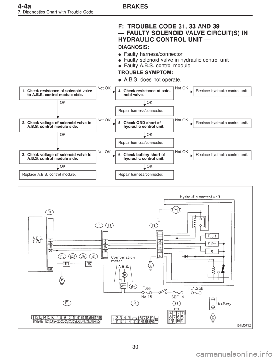
F: TROUBLE CODE 31, 33 AND 39
—FAULTY SOLENOID VALVE CIRCUIT(S) IN
HYDRAULIC CONTROL UNIT—
DIAGNOSIS:
�Faulty harness/connector
�Faulty solenoid valve in hydraulic control unit
�Faulty A.B.S. control module
TROUBLE SYMPTOM:
�A.B.S. does not operate.
1. Check resistance of solenoid valve
to A.B.S. control module side.
OK
�Not OK
4. Check resistance of sole-
noid valve.
OK
�Not OK
Replace hydraulic control unit.
Repair harness/connector.
2. Check voltage of solenoid valve to
A.B.S. control module side.
OK
�Not OK
5. Check GND short of
hydraulic control unit.
OK
�Not OK
Replace hydraulic control unit.
Repair harness/connector.
3. Check voltage of solenoid valve to
A.B.S. control module side.
OK
�Not OK
6. Check battery short of
hydraulic control unit.
OK
�Not OK
Replace hydraulic control unit.
Replace A.B.S. control module.Repair harness/connector.
B4M0712
�
�
�
�
��
30
4-4aBRAKES
7. Diagnostics Chart with Trouble Code
Page 1658 of 2248
 Turn ignition switch OFF.
2) Disconnect connector from A.B.S. control module.
3) Measure resistance between A.B.S. cont")
B4M0256B
1. CHECK RESISTANCE OF SOLENOID VALVE TO
A.B.S. CONTROL MODULE SIDE.
1) Turn ignition switch OFF.
2) Disconnect connector from A.B.S. control module.
3) Measure resistance between A.B.S. control module
connector terminals.
TROUBLE CODE / Connector & terminal:
31 / (P3) No. 35—No. 32
33 / (P3) No. 2—No. 32
39 / (P3) No. 18—No. 32
Specified resistance: approx. 1Ω
B4M0257B
2. CHECK VOLTAGE OF SOLENOID VALVE TO A.B.S.
CONTROL MODULE SIDE.
1) Turn ignition switch OFF.
2) Disconnect valve relay from hydraulic control unit.
3) Turn ignition switch ON.
4) Measure voltage between A.B.S. control module con-
nector terminals.
TROUBLE CODE / Connector & terminal:
31 / (P3) No. 35—No. 20
33 / (P3) No. 2—No. 20
39 / (P3) No. 18—No. 20
Specified voltage: 10—12 V
B4M0257B
3. CHECK VOLTAGE OF SOLENOID VALVE TO A.B.S.
CONTROL MODULE SIDE.
1) Turn ignition switch OFF.
2) Disconnect combination meter fuse No. 15.
3) Turn ignition switch ON.
4) Measure voltage between A.B.S. control module con-
nector terminals.
TROUBLE CODE / Connector & terminal:
31 / (P3) No. 35—No. 20
33 / (P3) No. 2—No. 20
39 / (P3) No. 18—No. 20
Specified voltage: 0 V
31
4-4aBRAKES
7. Diagnostics Chart with Trouble Code
Page 1659 of 2248
 Turn ignition switch OFF.
2) Disconnect connector from hydraulic control unit.
3) Measure resistance between hydraulic control unit ter-
minals.
TROU")
B4M0259B
4. CHECK RESISTANCE OF SOLENOID VALVE.
1) Turn ignition switch OFF.
2) Disconnect connector from hydraulic control unit.
3) Measure resistance between hydraulic control unit ter-
minals.
TROUBLE CODE / Connector & terminal:
31 / to (F9) No. 4—No. 11
33 / to (F9) No. 3—No. 11
39 / to (F9) No. 1—No. 11
Specified resistance: approx. 1Ω
B4M0702A
5. CHECK GND SHORT OF HYDRAULIC CONTROL
UNIT.
1) Turn ignition switch OFF.
2) Disconnect connector from hydraulic control unit.
3) Measure resistance between hydraulic control unit ter-
minals.
Connector & terminal / Specified resistance:
(F9) No. 11—body/1MΩ
(F9) No. 11—No.8/1MΩ
B4M0259B
B4M0703A
6. CHECK BATTERY SHORT OF HYDRAULIC
CONTROL UNIT.
1) Turn ignition switch OFF.
2) Disconnect connector from hydraulic control unit.
3) Measure resistance between hydraulic control unit ter-
minals.
TROUBLE CODE / Connector & terminal:
31 / to (F9) No. 4—No. 11
33 / to (F9) No. 3—No. 11
39 / to (F9) No. 1—No. 11
Specified resistance: approx. 1Ω
4) Turn ignition ON.
5) Measure voltage between hydraulic control unit termi-
nals.
Connector & terminal / Specified voltage:
(F9) No. 11—body/0V
32
4-4aBRAKES
7. Diagnostics Chart with Trouble Code
Page 1661 of 2248
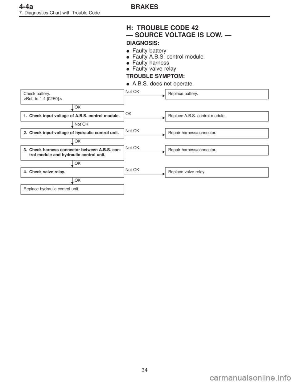
H: TROUBLE CODE 42
—SOURCE VOLTAGE IS LOW.—
DIAGNOSIS:
�Faulty battery
�Faulty A.B.S. control module
�Faulty harness
�Faulty valve relay
TROUBLE SYMPTOM:
�A.B.S. does not operate.
Check battery.
OK
�Not OK
Replace battery.
1. Check input voltage of A.B.S. control module.
Not OK
�OK
Replace A.B.S. control module.
2. Check input voltage of hydraulic control unit.
OK
�Not OK
Repair harness/connector.
3. Check harness connector between A.B.S. con-
trol module and hydraulic control unit.
OK
�Not OK
Repair harness/connector.
4. Check valve relay.
OK
�Not OK
Replace valve relay.
Replace hydraulic control unit.
�
�
�
�
�
34
4-4aBRAKES
7. Diagnostics Chart with Trouble Code
Page 1663 of 2248
 Turn ignition switch OFF.
2) Disconnect connector from hydraulic control unit.
3) Turn ignition switch ON.
4) Measure input voltage betwee")
B4M0262B
2. CHECK INPUT VOLTAGE OF HYDRAULIC
CONTROL UNIT.
1) Turn ignition switch OFF.
2) Disconnect connector from hydraulic control unit.
3) Turn ignition switch ON.
4) Measure input voltage between hydraulic control unit
connector and body.
Connector & terminal / Specified voltage:
(F8) No. 1—Body / 10—12 V
B4M0263B
3. CHECK HARNESS CONNECTOR BETWEEN A.B.S.
CONTROL MODULE AND HYDRAULIC CONTROL
UNIT.
1) Turn ignition switch OFF.
2) Disconnect connector from A.B.S. control module and
hydraulic control unit.
3) Measure resistance between A.B.S. control module and
hydraulic control unit.
Connector & terminal / Specified resistance:
(P3) No. 32—(F9) No. 11 / 0Ω
G4M0690
4. CHECK VALVE RELAY.
1) Remove valve relay.
2) Attach circuit tester probes to terminals, as shown in
figure.
3) Measure resistance between respective terminals.
Terminal / Specified resistance:
No. 87—No. 30 / 0Ω(when 12 volts applied.)
No. 87—No.30/1MΩ(when no volts applied.)
No. 87a—No.30/1MΩ(when 12 volts applied.)
No. 87a—No. 30 / 0Ω(when no volts applied.)
36
4-4aBRAKES
7. Diagnostics Chart with Trouble Code