Page 1727 of 2248
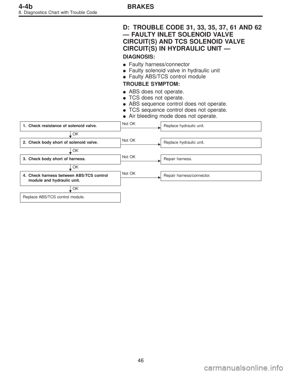
D: TROUBLE CODE 31, 33, 35, 37, 61 AND 62
—FAULTY INLET SOLENOID VALVE
CIRCUIT(S) AND TCS SOLENOID VALVE
CIRCUIT(S) IN HYDRAULIC UNIT—
DIAGNOSIS:
�Faulty harness/connector
�Faulty solenoid valve in hydraulic unit
�Faulty ABS/TCS control module
TROUBLE SYMPTOM:
�ABS does not operate.
�TCS does not operate.
�ABS sequence control does not operate.
�TCS sequence control does not operate.
�Air bleeding mode does not operate.
1. Check resistance of solenoid valve.
OK
�Not OK
Replace hydraulic unit.
2. Check body short of solenoid valve.
OK
�Not OK
Replace hydraulic unit.
3. Check body short of harness.
OK
�Not OK
Repair harness.
4. Check harness between ABS/TCS control
module and hydraulic unit.
OK
�Not OK
Repair harness/connector.
Replace ABS/TCS control module.
�
�
�
�
46
4-4bBRAKES
8. Diagnostics Chart with Trouble Code
Page 1729 of 2248
 Turn ignition switch OFF.
2) Disconnect connector from hydraulic unit.
3) Measure resistance between hydraulic unit terminals.
TROUBLE CODE / Connect")
B4M0723A
2. CHECK BODY SHORT OF SOLENOID VALVE.
1) Turn ignition switch OFF.
2) Disconnect connector from hydraulic unit.
3) Measure resistance between hydraulic unit terminals.
TROUBLE CODE / Connector & terminal:
31 / (F15) No. 3—body
33 / (F15) No. 4—body
35 / (F15) No. 1—body
37 / (F15) No. 2—body
61 / (F15) No. 12—body
62 / (F15) No. 11—body
Specified resistance: 1 MΩor more
B4M0419A
3. CHECK BODY SHORT OF HARNESS.
1) Turn ignition switch OFF.
2) Disconnect connector from hydraulic unit.
3) Disconnect connector from ABS/TCS control module.
4) Measure resistance between ABS/TCS control module
connector terminals.
TROUBLE CODE / Connector & terminal:
31 / (P5) No. 2—body
33 / (P4) No. 2—body
35 / (P4) No. 4—body
37 / (P5) No. 7—body
61 / (P4) No. 5—body
62 / (P5) No. 6—body
Specified resistance: 1 MΩor more
B4M0420A
4. CHECK HARNESS BETWEEN ABS/TCS CONTROL
MODULE AND HYDRAULIC UNIT.
1) Turn ignition switch OFF.
2) Connect connector to hydraulic unit.
3) Disconnect connector from ABS/TCS control module.
4) Measure resistance between ABS/TCS control module
connector terminals.
TROUBLE CODE / Connector & terminal:
31 / (P5) No. 2—(P6) No. 6
33 / (P4) No. 2—(P6) No. 6
48
4-4bBRAKES
8. Diagnostics Chart with Trouble Code
Page 1731 of 2248
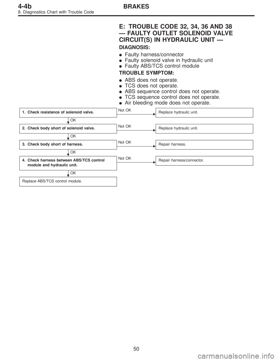
E: TROUBLE CODE 32, 34, 36 AND 38
—FAULTY OUTLET SOLENOID VALVE
CIRCUIT(S) IN HYDRAULIC UNIT—
DIAGNOSIS:
�Faulty harness/connector
�Faulty solenoid valve in hydraulic unit
�Faulty ABS/TCS control module
TROUBLE SYMPTOM:
�ABS does not operate.
�TCS does not operate.
�ABS sequence control does not operate.
�TCS sequence control does not operate.
�Air bleeding mode does not operate.
1. Check resistance of solenoid valve.
OK
�Not OK
Replace hydraulic unit.
2. Check body short of solenoid valve.
OK
�Not OK
Replace hydraulic unit.
3. Check body short of harness.
OK
�Not OK
Repair harness.
4. Check harness between ABS/TCS control
module and hydraulic unit.
OK
�Not OK
Repair harness/connector.
Replace ABS/TCS control module.
�
�
�
�
50
4-4bBRAKES
8. Diagnostics Chart with Trouble Code
Page 1733 of 2248
B4M0424A
3. CHECK BODY SHORT OF HARNESS.
1) Turn ignition switch OFF.
2) Disconnect connector from hydraulic unit.
3) Disconnect connector from ABS/TCS control module.
4) Measure resistance between ABS/TCS control module
connector terminals.
TROUBLE CODE / Connector & terminal:
32 / (P5) No. 3—body
34 / (P4) No. 1—body
36 / (P4) No. 3—body
38 / (P5) No. 8—body
Specified resistance: 1 MΩor more
B4M0425A
4. CHECK HARNESS BETWEEN ABS/TCS CONTROL
MODULE AND HYDRAULIC UNIT.
1) Turn ignition switch OFF.
2) Connect connector to hydraulic unit.
3) Disconnect connector from ABS/TCS control module.
4) Measure resistance between ABS/TCS control module
connector terminals.
TROUBLE CODE / Connector & terminal:
32 / (P5) No. 3—(P6) No. 6
34 / (P4) No. 1—(P6) No. 6
36 / (P4) No. 3—(P6) No. 6
38 / (P5) No. 8—(P6) No. 6
Specified resistance: 3.7±1.0Ω
52
4-4bBRAKES
8. Diagnostics Chart with Trouble Code
Page 1747 of 2248

J: TROUBLE CODE 52
—FAULTY MOTOR, MOTOR SENSOR AND/
OR MOTOR RELAY—
DIAGNOSIS:
�Faulty motor relay
�Faulty motor
�Faulty motor sensor
�Faulty harness/connector
�Faulty ABS/TCS control module
TROUBLE SYMPTOM:
�ABS does not operate.
�TCS does not operate.
1. Check resistance of motor relay.
OK
�Not OK
Replace motor relay.
2. Check input voltage of motor relay.
OK
�Not OK
Repair harness/connector.
3. Check body short of harness.
OK
�Not OK
Repair harness.
4. Check harness between ABS/TCS control
module and motor relay.
OK
�Not OK
Repair harness/connector.
5. Check motor operation.
OK
�Not OK
Go to step 10.
6. Check resistance of motor sensor.
OK
�Not OK
Replace hydraulic unit.
7. Check body short of motor sensor.
OK
�Not OK
Replace hydraulic unit.
8. Check harness between ABS/TCS control
module and motor sensor.
OK
�Not OK
Repair harness/connector.
9. Check body short of motor sensor harness.
OK
�Not OK
Repair harness.
Replace ABS/TCS control module.
�
�
�
�
�
�
�
�
�
66
4-4bBRAKES
8. Diagnostics Chart with Trouble Code
Page 1753 of 2248
K: TROUBLE CODE 54
—FAULTY STROKE SENSOR AND/OR STOP
LIGHT SWITCH—
DIAGNOSIS:
�Faulty stroke sensor
�Faulty stop light switch
�Faulty pump unit in hydraulic unit
�Faulty ABS/TCS control module
�Faulty harness/connector
TROUBLE SYMPTOM:
�ABS and TCS do not operate.
�No kick-back ocuurs while ABS is functioning.
�Only when the stop light switch circuit is broken, the ABS
functions while TCS does not. (TCS warning light only illu-
minates.)
72
4-4bBRAKES
8. Diagnostics Chart with Trouble Code
Page 1754 of 2248

1. Check correct installation of stroke sensor.
OK
�Not OK
Repair stroke sensor.
2. Check resistance of stroke sensor.
OK
�Not OK
Replace stroke sensor.
3. Check stroke sensor operation.
OK
�Not OK
Replace stroke sensor.
4. Check body short of stroke sensor.
OK
�Not OK
Replace stroke sensor.
5. Check contact point of stop light switch.
OK
�Not OK
Replace stroke sensor.
6. Check body short of stop light switch.
OK
�Not OK
Replace stroke sensor.
7. Check power supply of stop light switch.
OK
�Not OK
Repair harness/connector.
8. Check input voltage of ABS/TCS control mod-
ule.
OK
�Not OK
Repair harness/connector.
9. Check stop light circuit.
OK
�Not OK
Repair harness/connector.
Replace stop light bulb and/or fuse.
10. Check harness between stroke sensor and
ABS/TCS control module.
OK
�Not OK
Repair harness/connector.
11. Check body short of stroke sensor harness.
OK
�Not OK
Repair harness.
12. Check pump unit operation.
OK
�Not OK
Replace hydraulic unit.
Replace ABS/TCS control module.
�
�
�
�
�
�
�
�
�
�
�
�
73
4-4bBRAKES
8. Diagnostics Chart with Trouble Code
Page 1758 of 2248
 Turn ignition switch OFF.
2) Install stroke sensor.
3) Connect stroke sensor connector.
4) Disconnect ABS/TCS control mo")
B4M0470A
10. CHECK HARNESS BETWEEN STROKE SENSOR
AND ABS/TCS CONTROL MODULE.
1) Turn ignition switch OFF.
2) Install stroke sensor.
3) Connect stroke sensor connector.
4) Disconnect ABS/TCS control module connector.
5) Measure resistance between ABS/TCS control module
connector terminals.
Connector & terminal / Specified resistance:
(P7) No. 4—No. 14 / 570—630Ω
(P7) No. 5—No. 14 / 95—105Ω
NOTE:
Do not depress brake pedal.
B4M0471A
11. CHECK BODY SHORT OF STROKE SENSOR
HARNESS.
1) Turn ignition switch OFF.
2) Connect stroke sensor connector.
3) Disconnect ABS/TCS control module connector.
4) Measure resistance between ABS/TCS control module
connector and body.
Connector & terminal / Specified resistance:
(P7) No. 4—body/1MΩor more
(P7) No. 5—body/1MΩor more
(P7) No. 14—body/1MΩor more
12. CHECK PUMP UNIT OPERATION.
1) Turn ignition switch OFF.
2) Connect stroke sensor connector.
3) Connect stop light switch connector.
4) Connect ABS/TCS control module connector.
5) Operate the TCS sequence control and check that the
front brake fluid pressure increases and decreases cor-
rectly.
77
4-4bBRAKES
8. Diagnostics Chart with Trouble Code
 Turn ignition switch OFF.
2) Disconnect connector from hydraulic unit.
3) Disconnect connector from ABS/TCS control module.
4) Measure resistance between AB")