Page 1789 of 2248

B4M0512
M: TROUBLE CODE 32
FR.OUT VALVE
—Faulty front right outlet solenoid valve—
DIAGNOSIS:
�Faulty harness/connector
�Faulty solenoid valve in hydraulic unit
�Faulty ABS/TCS control module
TROUBLE SYMPTOM:
�ABS and TCS do not operate.
�ABS sequence control does not operate.
�TCS sequence control does not operate.
�Air bleeding mode does not operate.
1. Check resistance of solenoid valve.
OK
�Not OK
Replace hydraulic unit.
2. Check body short of solenoid valve.
OK
�Not OK
Replace hydraulic unit.
3. Check body short of harness.
OK
�Not OK
Repair harness.
4. Check harness between ABS/TCS control
module and hydraulic unit.
OK
�Not OK
Repair harness/connector.
Replace ABS/TCS control module.
B4M0513
N: TROUBLE CODE 33
FL.IN VALVE
—Faulty front left inlet solenoid valve—
DIAGNOSIS:
�Faulty harness/connector
�Faulty solenoid valve in hydraulic unit
�Faulty ABS/TCS control module
TROUBLE SYMPTOM:
�ABS and TCS do not operate.
�ABS sequence control does not operate.
�TCS sequence control does not operate.
�Air bleeding mode does not operate.
NOTE:
The procedures used are the same as those for FR.IN
VA LV E .
�
�
�
�
108
4-4bBRAKES
10. Diagnostic Chart with Select Monitor
Page 1790 of 2248
B4M0514
O: TROUBLE CODE 34
FL.OUT VALVE
—Faulty front left outlet solenoid valve—
DIAGNOSIS:
�Faulty harness/connector
�Faulty solenoid valve in hydraulic unit
�Faulty ABS/TCS control module
TROUBLE SYMPTOM:
�ABS and TCS do not operate.
�ABS sequence control does not operate.
�TCS sequence control does not operate.
�Air bleeding mode does not operate.
NOTE:
The procedures used are the same as those for FR.OUT
VA LV E .
B4M0515
P: TROUBLE CODE 35
RR.IN VALVE
—Faulty rear right inlet solenoid valve—
DIAGNOSIS:
�Faulty harness/connector
�Faulty solenoid valve in hydraulic unit
�Faulty ABS/TCS control module
TROUBLE SYMPTOM:
�ABS and TCS do not operate.
�ABS sequence control does not operate.
�TCS sequence control does not operate.
�Air bleeding mode does not operate.
NOTE:
The procedures used are the same as those for FR.IN
VA LV E .
109
4-4bBRAKES
10. Diagnostic Chart with Select Monitor
Page 1791 of 2248
B4M0516
Q: TROUBLE CODE 36
RR.OUT VALVE
—Faulty rear right outlet solenoid valve—
DIAGNOSIS:
�Faulty harness/connector
�Faulty solenoid valve in hydraulic unit
�Faulty ABS/TCS control module
TROUBLE SYMPTOM:
�ABS and TCS do not operate.
�ABS sequence control does not operate.
�TCS sequence control does not operate.
�Air bleeding mode does not operate.
NOTE:
The procedures used are the same as those for FR.OUT
VA LV E .
B4M0517
R: TROUBLE CODE 37
RL.IN VALVE
—Faulty rear left inlet solenoid valve—
DIAGNOSIS:
�Faulty harness/connector
�Faulty solenoid valve in hydraulic unit
�Faulty ABS/TCS control module
TROUBLE SYMPTOM:
�ABS and TCS do not operate.
�ABS sequence control does not operate.
�TCS sequence control does not operate.
�Air bleeding mode does not operate.
NOTE:
The procedures used are the same as those for FR.IN
VA LV E .
11 0
4-4bBRAKES
10. Diagnostic Chart with Select Monitor
Page 1792 of 2248

B4M0518
S: TROUBLE CODE 38
RL.OUT VALVE
—Faulty rear left outlet solenoid valve—
DIAGNOSIS:
�Faulty harness/connector
�Faulty solenoid valve in hydraulic unit
�Faulty ABS/TCS control module
TROUBLE SYMPTOM:
�ABS and TCS do not operate.
�ABS sequence control does not operate.
�TCS sequence control does not operate.
�Air bleeding mode does not operate.
NOTE:
The procedures used are the same as those for FR.OUT
VA LV E .
B4M0519
T: TROUBLE CODE 41
ECU
—Faulty ABS/TCS control module—
DIAGNOSIS:
�Faulty ABS/TCS control module
�Faulty harness/connector
TROUBLE SYMPTOM:
�ABS does not operate.
�TCS does not operate.
1. Check ground circuit of ABS/TCS control
module.
OK
�Not OK
Repair harness/connector.
2. Check harness connectors between power
supply generator, battery and ABS/TCS con-
trol module.
OK
�Not OK
Repair harness/connector.
3. Check sources of signal noise.
OK
�Not OK
Repair noise sources.
Replace ABS/TCS control module.
�
�
�
111
4-4bBRAKES
10. Diagnostic Chart with Select Monitor
Page 1797 of 2248
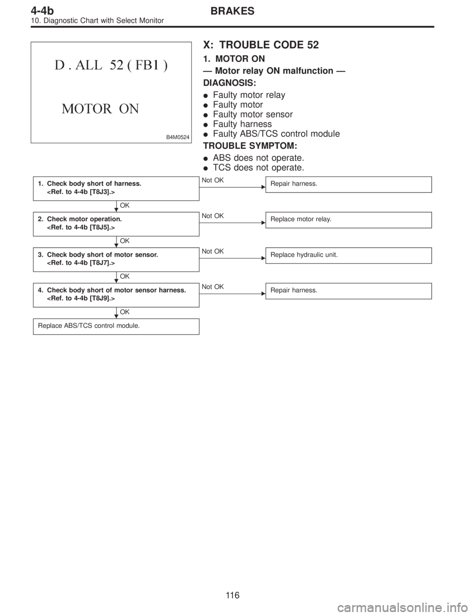
B4M0524
X: TROUBLE CODE 52
1. MOTOR ON
—Motor relay ON malfunction—
DIAGNOSIS:
�Faulty motor relay
�Faulty motor
�Faulty motor sensor
�Faulty harness
�Faulty ABS/TCS control module
TROUBLE SYMPTOM:
�ABS does not operate.
�TCS does not operate.
1. Check body short of harness.
OK
�Not OK
Repair harness.
2. Check motor operation.
OK
�Not OK
Replace motor relay.
3. Check body short of motor sensor.
OK
�Not OK
Replace hydraulic unit.
4. Check body short of motor sensor harness.
OK
�Not OK
Repair harness.
Replace ABS/TCS control module.
�
�
�
�
11 6
4-4bBRAKES
10. Diagnostic Chart with Select Monitor
Page 1798 of 2248
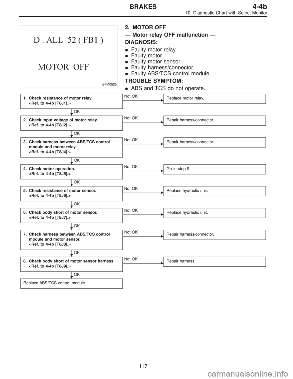
B4M0525
2. MOTOR OFF
—Motor relay OFF malfunction—
DIAGNOSIS:
�Faulty motor relay
�Faulty motor
�Faulty motor sensor
�Faulty harness/connector
�Faulty ABS/TCS control module
TROUBLE SYMPTOM:
�ABS and TCS do not operate.
1. Check resistance of motor relay.
OK
�Not OK
Replace motor relay.
2. Check input voltage of motor relay.
OK
�Not OK
Repair harness/connector.
3. Check harness between ABS/TCS control
module and motor relay.
OK
�Not OK
Repair harness/connector.
4. Check motor operation.
OK
�Not OK
Go to step 9.
5. Check resistance of motor sensor.
OK
�Not OK
Replace hydraulic unit.
6. Check body short of motor sensor.
OK
�Not OK
Replace hydraulic unit.
7. Check harness between ABS/TCS control
module and motor sensor.
OK
�Not OK
Repair harness/connector.
8. Check body short of motor sensor harness.
OK
�Not OK
Repair harness.
Replace ABS/TCS control module.
�
�
�
�
�
�
�
�
11 7
4-4bBRAKES
10. Diagnostic Chart with Select Monitor
Page 1799 of 2248
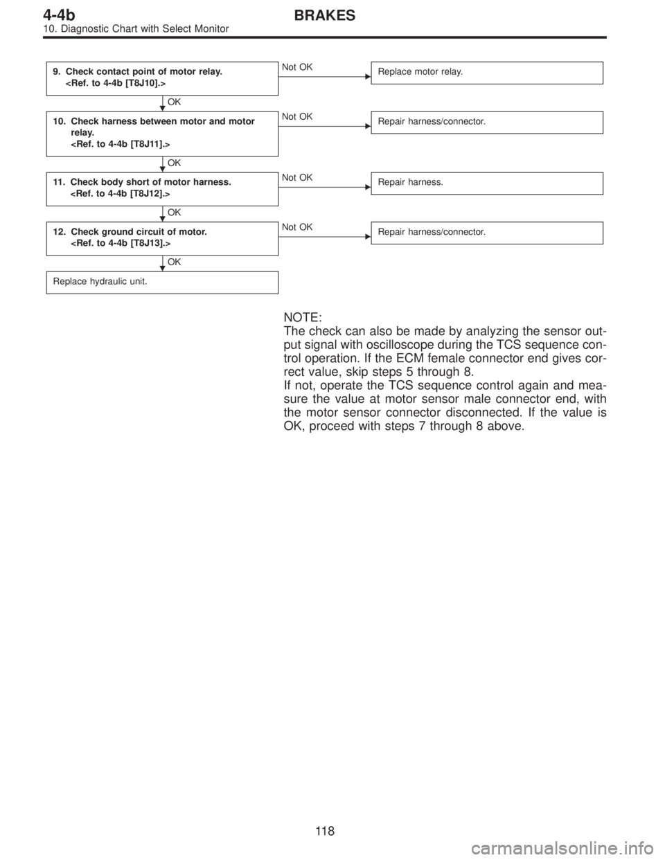
9. Check contact point of motor relay.
OK
�Not OK
Replace motor relay.
10. Check harness between motor and motor
relay.
OK
�Not OK
Repair harness/connector.
11. Check body short of motor harness.
OK
�Not OK
Repair harness.
12. Check ground circuit of motor.
OK
�Not OK
Repair harness/connector.
Replace hydraulic unit.
NOTE:
The check can also be made by analyzing the sensor out-
put signal with oscilloscope during the TCS sequence con-
trol operation. If the ECM female connector end gives cor-
rect value, skip steps 5 through 8.
If not, operate the TCS sequence control again and mea-
sure the value at motor sensor male connector end, with
the motor sensor connector disconnected. If the value is
OK, proceed with steps 7 through 8 above.
�
�
�
�
11 8
4-4bBRAKES
10. Diagnostic Chart with Select Monitor
Page 1803 of 2248

—Comparison between stroke sensor and pump
output—
DIAGNOSIS:
�Faulty stroke sensor
�Faulty harness/connector
�Faulty pump unit in hydraulic unit
�Faulty stop light switch")
B4M0529
4. B.SW SOFT (P)
—Comparison between stroke sensor and pump
output—
DIAGNOSIS:
�Faulty stroke sensor
�Faulty harness/connector
�Faulty pump unit in hydraulic unit
�Faulty stop light switch
�Faulty ABS/TCS control module
NOTE:
Operate the function F09 in select monitor TCS mode, and
read the sensor output step.
If system is normal, the output reading is 1 when brake
pedal is not depressed, and it changes from 2 to 3, 4 and
5 in accordance with the brake pedal depressing. If so, skip
check steps 2 through 4.
1. Check correct installation of stroke sensor.
OK
�Not OK
Repair stroke sensor.
2. Check resistance of stroke sensor.
OK
�Not OK
Replace stroke sensor.
3. Check stroke sensor operation.
OK
�Not OK
Replace stroke sensor.
4. Check harness between stroke sensor and
ABS/TCS control module.
OK
�Not OK
Repair harness/connector.
5. Check pump unit operation.
OK
�Not OK
Replace hydraulic unit.
Replace ABS/TCS control module.
�
�
�
�
�
122
4-4bBRAKES
10. Diagnostic Chart with Select Monitor